Construction method of shear resistance and strengthening of concrete box beams based on corrugated steel webs

A technology of corrugated steel webs and concrete box girders, applied in bridge reinforcement, bridges, bridge maintenance, etc., can solve the problems of affecting the appearance of the bridge, increasing the self-weight of the bridge, and the limited improvement of the shear bearing capacity, etc., to achieve structural and structural The effect of clear stress, prevention of concrete cracks, and performance improvement

Active Publication Date: 2015-06-10
HENAN PROVINCIAL TRANSPORTATION RES INST
View PDF6 Cites 0 Cited by
  • Summary
  • Abstract
  • Description
  • Claims
  • Application Information

AI Technical Summary

Problems solved by technology

However, due to deficiencies or defects in design, construction, and operation management, a large proportion of long-span prestressed concrete box girder bridges currently in service have web oblique cracks, which have directly threatened the durability and safety of bridges.
[0003] In order to restrain the further development of oblique cracks in the web and improve the shear resistance of the bridge, existing reinforcement methods include pasting steel plates or carbon fibers on the web of the box girder, tensioning the vertical prestress, and enlarging the cross-section of the web, etc. Among them, although the construction of pasting steel plates or carbon fibers is simple, the improvement of the shear bearing capacity is limited, and the aesthetics of the bridge is affected; the vertical tension prestress construction is difficult, and it faces problems such as prestress loss; The slab section will greatly increase the self-weight of the bridge, causing additional load effects on the bridge
Moreover, none of the above three methods can significantly improve the original shear force distribution state of the box girder web

Method used


Image

  • Construction method of shear resistance and strengthening of concrete box beams based on corrugated steel webs
  • Construction method of shear resistance and strengthening of concrete box beams based on corrugated steel webs
  • Construction method of shear resistance and strengthening of concrete box beams based on corrugated steel webs

Examples


Embodiment Construction

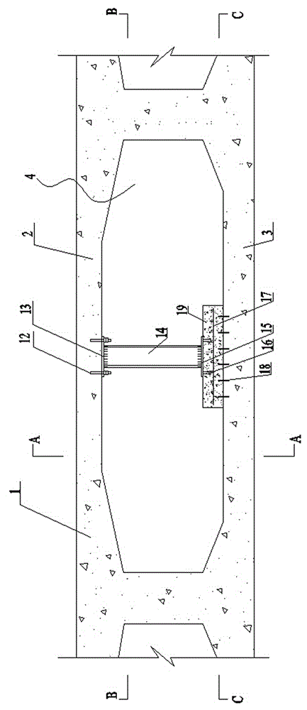
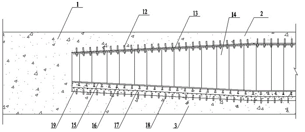
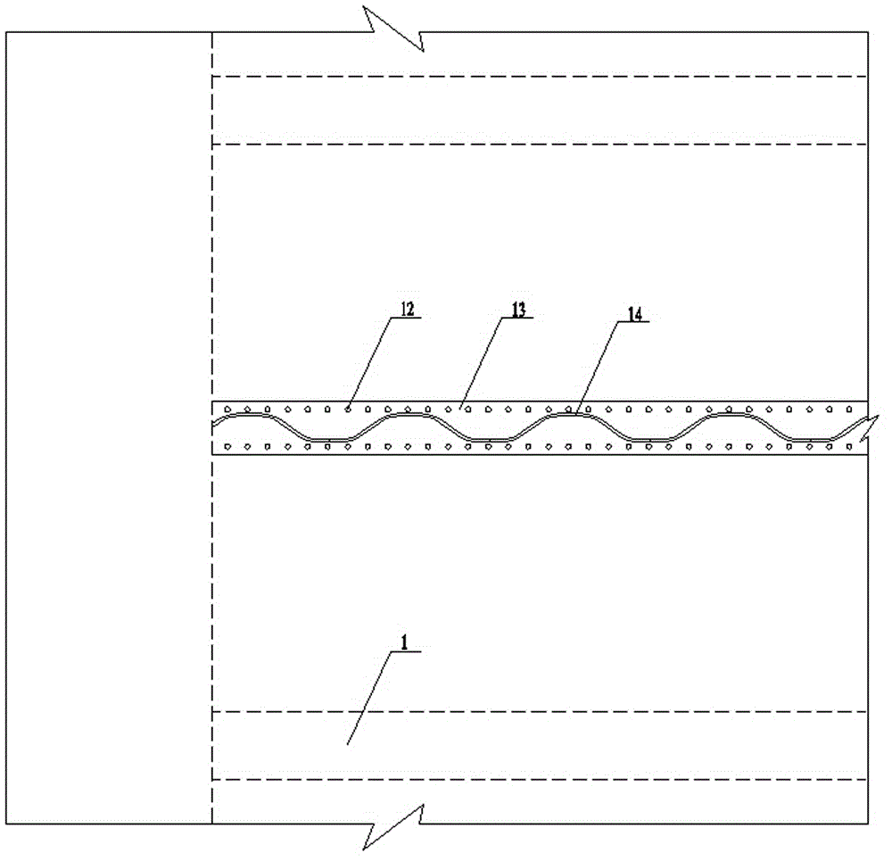
[0025] Anchor bolt 12 selects chemical anchor bolt in the present embodiment, combines Figure 1 to Figure 4 Shown, the construction method of the concrete box girder shear reinforcement based on the corrugated steel web of the present invention, carries out by following steps successively:

[0026] 1) Carry out construction lofting and positioning on the box girder top plate 2 and box girder bottom plate 3: determine the following positions through this lofting: the center line of the longitudinal box girder box chamber 4, that is, the center direction of the corrugated steel web; the anchor bolts embedded in the box girder top plate Hole location; box girder bottom slab planting reinforcement location; post-cast concrete vertical formwork location;

[0027] 2) Treatment of the reinforcement joint surface: Grinding, cleaning and dust removal are performed on the reinforcement joint surface area of ​​the box girder top plate 2 and the box girder bottom plate 3. Under certain ...


PUM


Abstract

The invention discloses a construction method of shear resistance and strengthening of concrete box beams based on corrugated steel webs. The construction method successively comprises the following steps: performing construction lofting and positioning on top plates and bottom plates of box beams; performing and strengthening bonding surfaces; drilling anchor bolt holes in the bottom surfaces of the top plates of the box beams; drilling holes and planting steel bars in the top surfaces of the bottom plates of the box beams; performing laying-off on the corrugated steel webs; drilling holes and performing polishing on upper flange plates; welding and mounting the corrugated steel webs; mounting reinforced mesh slices; erecting a model and pouring concrete. The construction method disclosed by the invention has the advantage that the purposes of shear resistance and strengthening of the concrete box beams are achieved by mounting longitudinal corrugated steel web components in box chambers of box beams, increasing the number of webs of the box beams and reducing the main tensile stress of original concrete webs of the box beams.

Description

technical field [0001] The invention belongs to the technical field of bridge engineering, and in particular relates to a construction method for shear reinforcement of concrete box girders based on corrugated steel webs. Background technique [0002] At present, the concrete box girder bridge has become one of the main types of long-span bridges in my country. However, due to deficiencies or defects in design, construction, and operation management, a large proportion of long-span prestressed concrete box girder bridges currently in service have web oblique cracks, which have directly threatened the durability and safety of bridges. [0003] In order to restrain the further development of oblique cracks in the web and improve the shear resistance of the bridge, existing reinforcement methods include pasting steel plates or carbon fibers on the web of the box girder, tensioning the vertical prestress, and enlarging the cross-section of the web, etc. Among them, although the...

Claims


Application Information

Patent Timeline
Patent Type & Authority Applications(China)
IPC IPC(8): E01D22/00
CPCE01D2/04E01D22/00
Inventor 王统宁唐国斌付立军吕小武胡锋程坤张建龙
Owner HENAN PROVINCIAL TRANSPORTATION RES INST
Why Eureka
Try Eureka