Construction method for carrying out shear strengthening on concrete box girder by adopting corrugated steel web

A technology of corrugated steel webs and concrete box girders, applied in bridge reinforcement, bridges, bridge construction, etc., can solve the problems of affecting the appearance of the bridge, increasing the self-weight of the bridge, and the limited improvement of the shear bearing capacity, etc., to achieve structural and structural The effect of clear stress, prevention of concrete cracks, and improvement of concrete performance

Active Publication Date: 2015-06-10
HENAN PROVINCIAL TRANSPORTATION RES INST
View PDF3 Cites 3 Cited by
  • Summary
  • Abstract
  • Description
  • Claims
  • Application Information

AI Technical Summary

Problems solved by technology

However, due to deficiencies or defects in design, construction, and operation management, a large proportion of long-span prestressed concrete box girder bridges currently in service have web oblique cracks, which have directly threatened the durability and safety of bridges.
[0003] In order to restrain the further development of oblique cracks in the web and improve the shear resistance of the bridge, existing reinforcement methods include pasting steel plates or carbon fibers on the web of the box girder, tensioning the vertical prestress, and enlarging the cross-section of the web, etc. Among them, although the construction of pasting steel plates or carbon fibers is simple, the improvement of the shear bearing capacity is limited, and the aesthetics of the bridge is affected; the vertical tension prestress construction is difficult, and it faces problems such as prestress loss; The slab section will greatly increase the self-weight of the bridge, causing additional load effects on the bridge
Moreover, none of the above three methods can significantly improve the original shear force distribution state of the box girder web

Method used


Image

  • Construction method for carrying out shear strengthening on concrete box girder by adopting corrugated steel web
  • Construction method for carrying out shear strengthening on concrete box girder by adopting corrugated steel web
  • Construction method for carrying out shear strengthening on concrete box girder by adopting corrugated steel web

Examples


Embodiment Construction

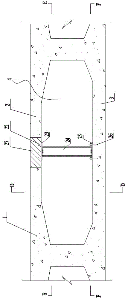
[0023] Anchor bolt 26 selects chemical anchor bolt in the present embodiment, combines Figure 1 to Figure 4 Shown, adopt corrugated steel web of the present invention to carry out the construction method of concrete box girder anti-shear reinforcement, carry out according to the following steps successively:

[0024] 1) Carry out construction lofting and positioning on the box girder top plate 2 and box girder bottom plate 3: determine the following positions through the lofting: the center line of the longitudinal box girder box chamber 4, that is, the center direction of the corrugated steel web; the opening size of the box girder top plate; The location of the anchor bolt holes in the bottom plate of the box girder;

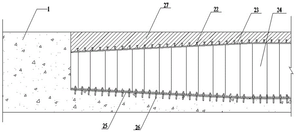
[0025] 2) Opening of box girder roof 2: according to step 1) the opening size of the box girder roof for lofting and positioning, chisel away the concrete of box girder roof 2 within the range of lofting, and avoid damage to the original steel bars during the...


PUM


Abstract

The invention discloses a construction method for carrying out shear strengthening on a concrete box girder by adopting a corrugated steel web. The construction method sequentially comprises the following steps: performing construction layout positioning on a box girder top plate and a box girder bottom plate; forming a hole in the box girder top plate; processing and strengthening a junction surface; drilling an anchor bolt hole in the top surface of the box girder bottom plate; blanking the corrugated steel web; drilling a hole in a lower flange plate, and polishing the lower flange plate; welding and mounting the corrugated steel web; pouring concrete into the hole of the box girder top plate. The construction method has the advantages that by mounting a longitudinal corrugated steel web component in a box chamber of a box girder, the number of webs of the box girder is increased, and the principal tensile stress of an original concrete web of the box girder is reduced, so that the aim of shear strengthening of a box girder bridge is achieved.

Description

technical field [0001] The invention belongs to the technical field of bridge engineering, and in particular relates to a construction method for shearing reinforcement of concrete box girders by using corrugated steel webs. Background technique [0002] At present, the concrete box girder bridge has become one of the main types of long-span bridges in my country. However, due to deficiencies or defects in design, construction, and operation management, a large proportion of long-span prestressed concrete box girder bridges currently in service have web oblique cracks, which have directly threatened the durability and safety of bridges. [0003] In order to restrain the further development of oblique cracks in the web and improve the shear resistance of the bridge, existing reinforcement methods include pasting steel plates or carbon fibers on the web of the box girder, tensioning the vertical prestress, and enlarging the cross-section of the web, etc. Among them, although ...

Claims


Application Information

Patent Timeline
Patent Type & Authority Applications(China)
IPC IPC(8): E01D22/00
CPCE01D22/00
Inventor 王统宁唐国斌付立军吕小武胡锋程坤张建龙
Owner HENAN PROVINCIAL TRANSPORTATION RES INST
Why Eureka
Try Eureka