
Multipurpose expansion tank

A technology for expansion tanks and tanks, which is applied in water saving, water supply devices, water supply pool configuration, etc., can solve the problems of reducing the power of water pumps, reducing the installation space of pipelines, and many installation points, etc., to achieve functional requirements and structural principles Simple and clear effect

Active Publication Date: 2017-09-01
江苏亚星波纹管有限公司
View PDF6 Cites 0 Cited by
  • Summary
  • Abstract
  • Description
  • Claims
  • Application Information

AI Technical Summary

Problems solved by technology

[0003] Nowadays, energy conservation is becoming more and more important, and in response to the requirements of national policies, energy-saving transformations are being carried out on traditional circulating water systems. One of them is how to reduce the power of water pumps under the premise of ensuring flow pressure. In many Exhaust, pressure stabilization, constant pressure, temporary filling and other equipment are used in all transformation methods. However, due to too many installation points during installation, while increasing resistance, the installation space of pipelines is still reduced.

Method used


Image

  • Multipurpose expansion tank

Examples


Embodiment 1

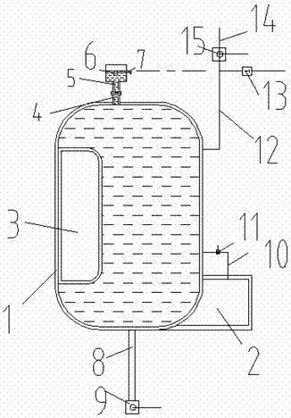
[0014] Such as figure 1 As shown, a multi-purpose expansion tank includes an expansion tank body 1, a drain tank 2, an airbag chamber 3, an exhaust port flange tube 4, an exhaust tank 5, a float valve 6, an exhaust pipe 7, an outlet pipe 8, Shutoff valve A9, drain pipe 10, shutoff valve B11, water inlet pipe 12, check valve 13, medicine adding branch pipe 14, shutoff valve C15.

[0015] The drain tank 2 is located at the lower end of the expansion tank 1 and is fixedly connected to the outer surface of the expansion tank 1. The drain tank 2 is mainly used to drain the water filled in the tank by opening the shut-off valve B11 when it is necessary to add medicine. , Reserve a certain water level in the water tank to fill the liquid medicine.

[0016] The airbag chamber 3 is located inside the expansion tank 1, and is fixedly connected to the inner wall of the expansion tank 1. The inner side of the airbag is fixed in the expansion water tank 1 through a sealing plate, and the ...

Embodiment 2

[0025] Such as figure 1 As shown, a multi-purpose expansion tank includes an expansion tank body 1, a drain tank 2, an airbag chamber 3, an exhaust port flange tube 4, an exhaust tank 5, a float valve 6, an exhaust pipe 7, an outlet pipe 8, Shutoff valve A9, drain pipe 10, shutoff valve B11, water inlet pipe 12, check valve 13, medicine adding branch pipe 14, shutoff valve C15.

[0026] The drain tank 2 is located at the lower end of the expansion tank 1 and is fixedly connected to the outer surface of the expansion tank 1. The drain tank 2 is mainly used to drain the water filled in the tank by opening the shut-off valve B11 when it is necessary to add medicine. , Reserve a certain water level in the water tank to fill the liquid medicine.

[0027] The airbag chamber 3 is located inside the expansion tank 1, and is fixedly connected to the inner wall of the expansion tank 1. The inner side of the airbag is fixed in the expansion water tank 1 through a sealing plate, and the ...


PUM


Abstract

The invention discloses a multipurpose expansion tank comprising an expansion tank body, a water drain channel, an air bag cavity, an exhaust port flange pipe, an exhaust pot, a floating ball valve, an exhaust pipe, a water outlet pipe, a turn-off valve A, a water drain pipe, a turn-off valve B, a water inlet pipe, a check valve, a branch medicating pipe and a turn-off valve C. The multipurpose expansion tank is simple and clear in structure principle, different equipment combinations can be switched according to needs through cooperation between the different pipes and the turn-off valves and combination of internal and external equipment, and accordingly a functional requirement of an energy-saving closed recirculating system is met.

Description

technical field [0001] The invention relates to a multi-purpose expansion water tank, in particular to a functional water tank with multiple purposes such as exhaust, pressure stabilization and filling. Background technique [0002] In the closed circulating water tank, there are certain requirements for the pressure of the inlet and outlet of the equipment everywhere. In the traditional system, the pressure of the system is completely guaranteed by the outlet head of the water pump. [0003] Nowadays, energy conservation is becoming more and more important, and in response to the requirements of national policies, energy-saving transformations are being carried out on traditional circulating water systems. One of them is how to reduce the power of water pumps under the premise of ensuring flow pressure. In many Exhaust, pressure stabilization, constant pressure, temporary filling and other equipment are used in all transformation methods, but due to too many installation po...

Claims


Application Information

Patent Timeline
Patent Type & Authority Patents(China)
IPC IPC(8): E03B11/06
CPCE03B11/06Y02A20/00
Inventor 朱根龙
Owner 江苏亚星波纹管有限公司
Learn More