Thermal shrinkage bonding nut structure

A nut and heat-shrinkable technology, which is applied in the direction of nuts, screws, bolts, etc., can solve the problems of easy falling off of nuts and the cost of nail planting, and achieve the effect of avoiding insufficient bite force and easy falling off, saving costs and avoiding high costs

Inactive Publication Date: 2015-06-10
SHENXUN COMP KUNSHAN
View PDF5 Cites 5 Cited by
  • Summary
  • Abstract
  • Description
  • Claims
  • Application Information

AI Technical Summary

Problems solved by technology

[0006] Therefore, the object of the present invention is to provide a heat-shrinkable bonded nut structure

Method used


Image

  • Thermal shrinkage bonding nut structure
  • Thermal shrinkage bonding nut structure
  • Thermal shrinkage bonding nut structure

Examples


Embodiment Construction

[0021] The specific implementation manners of the present invention will be described in further detail below in conjunction with the accompanying drawings.

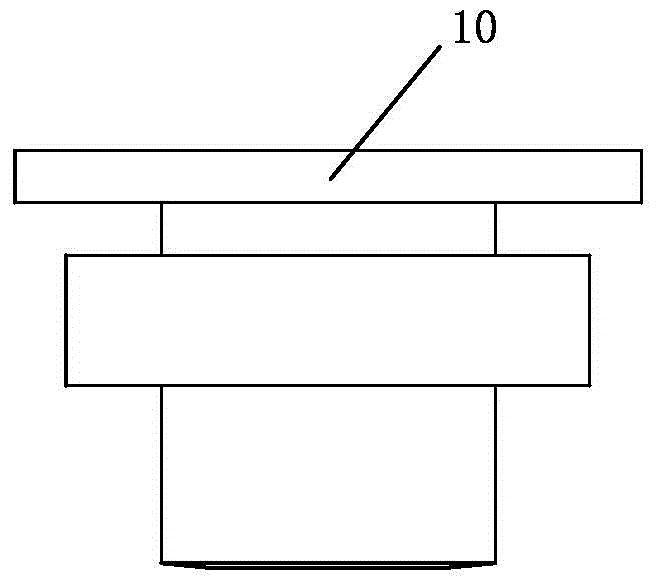
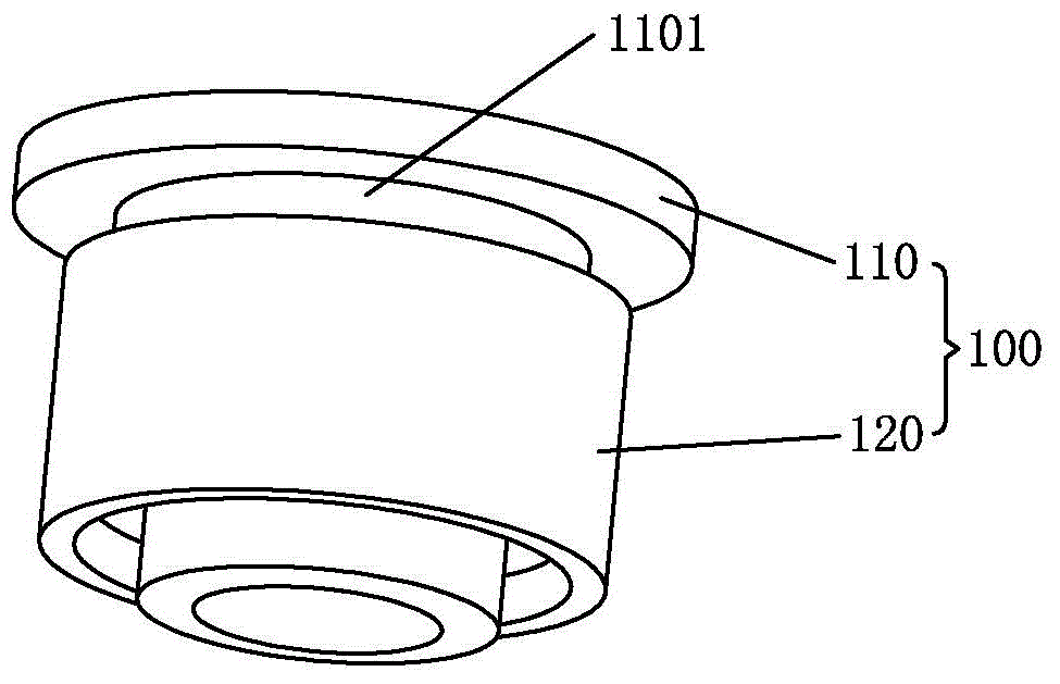
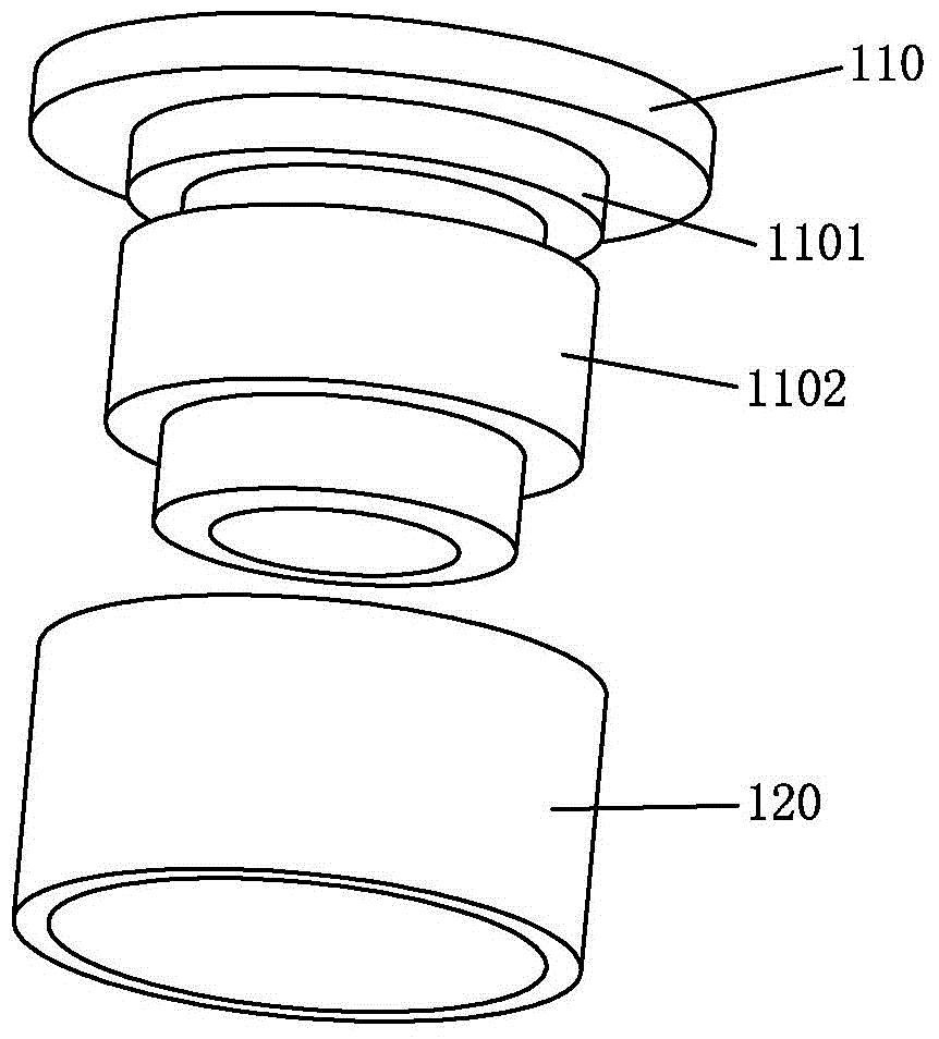
[0022] For this purpose, please refer to the figure 2 and image 3 As shown, the heat-shrinkable adhesive nut structure 100 provided by the present invention is implanted in the screw column 200 for locking screws, and the heat-shrinkable adhesive nut structure 100 includes:

[0023] Nut 110, the inside of which is hollow cylindrical, the outer periphery of the nut 110 has a first raised portion 1101 and a second raised portion 1102 arranged parallel thereto, and the outer diameter R1 of the nut 110 is smaller than that of the screw column 200 Inner diameter R2;

[0024] The heat shrinkable tube 120 is sheathed on the second protruding portion 1102 .

[0025] In this embodiment, after the nail is implanted, the inside of the heat-shrinkable tube 120 is in close contact with the second protrusion 1102 .

[0026] In t...


PUM


Abstract

The invention discloses a thermal shrinkage bonding nut structure, wherein the thermal shrinkage bonding nut structure is implanted in a screw stud to lock a screw. The thermal shrinkage bonding nut structure structurally comprises a nut and a thermal shrinkage tube, wherein the interior of the nut takes the shape of a hollow cylinder, a first bulge part and a second bulge part parallel with the first bulge part are arranged at the periphery of the nut, the outer diameter of the nut is smaller than the inner diameter of the screw stud, and the thermal shrinkage tube is arranged on the second bulge part in a sleeving manner. According to the thermal shrinkage bonding nut structure, the thermal shrinkage tube is added, then the nut and the screw stud are more tightly and stably connected, and the problem that a common nut falls off easily because of the insufficient interlocking force is avoided. Meanwhile, a relatively large interlocking force is acquired only through a traditional hot-melting nut implantation method, so that the problem of high cost of a simultaneous die-sinking implantation method is avoided, and the cost is further reduced.

Description

【Technical field】 [0001] The invention relates to a hardware connection workpiece, in particular to a heat-shrinkable bonded nut structure. 【Background technique】 [0002] At present, most of the shells of 3C products are molded by plastic. To make plastic into products, it is inevitable to use nails, that is, to embed nuts into plastic parts, so that screws can pass through the nuts. It is convenient to lock the matching shells together. [0003] see figure 1 As shown, the nut 10 is a commonly used common nut. Usually, the outer diameter of the nut 10 is larger than the inner diameter of the screw column. Therefore, the traditional nail planting method is to firstly heat the nut and then use its heat conduction principle to indirectly heat the screw column. As a result, the screw post with plastic material will engage with the teeth around the nut after melting, so as to achieve the purpose of implanting the nut into the screw post. In the case of poor meltability, poor ...

Claims


Application Information

Patent Timeline
IPC IPC(8): F16B39/02
CPCF16B39/02
Inventor 张祥
Owner SHENXUN COMP KUNSHAN
Why Eureka
Try Eureka