A device and method for measuring flow two-dimensional velocity field based on near-field scattering

A technology of measuring device and velocity field, which is applied in the direction of fluid velocity measurement, measuring device, velocity/acceleration/shock measurement, etc. It can solve problems such as expensive, complex equipment, and large system interference, and achieve low requirements for optical path alignment. The effect of simple measurement device and simple data analysis

Active Publication Date: 2018-01-02
SOUTHEAST UNIV
View PDF5 Cites 2 Cited by
  • Summary
  • Abstract
  • Description
  • Claims
  • Application Information

AI Technical Summary

Problems solved by technology

PIV is a very important measurement technique developed in the 1980s to study fluid dynamics. However, due to the great limitation on the concentration of tracer particles in the flow field, the spatial resolution of the flow field measured by the experiment is not ideal. The current commercialized PIV instruments are complex and expensive, which greatly limits the application and development of PIV measuring instruments
The subsequently developed HPIV is a speed measurement technology that is improved on the original PIV technology and can be used to measure the distribution of the three-dimensional velocity field. However, the device of this technology is relatively complicated, the data processing has lag, and the realization of online measurement is difficult.
In addition, when the particle concentration of the experiment is too high, the speckle noise will seriously affect the interference imaging effect and particle identification
[0004] The particle size and concentration of the tracer particles added to the fluid restrict the existing measurement techniques above. Whether it is LSV or PIV (HPIV), the particle size of the tracer particles used should not be too small and the concentration should not be too high, otherwise it will not be possible Ensure the accuracy and linearity of the system, and the interference of stray light to the system is also large

Method used


Image

  • A device and method for measuring flow two-dimensional velocity field based on near-field scattering
  • A device and method for measuring flow two-dimensional velocity field based on near-field scattering
  • A device and method for measuring flow two-dimensional velocity field based on near-field scattering

Examples


Embodiment Construction

[0037] The present invention will be further explained below in conjunction with the accompanying drawings and specific embodiments. It should be understood that these embodiments are only used to illustrate the present invention and are not intended to limit the scope of the present invention. After reading the present invention, those skilled in the art all fall into the appended claims of the present application to the amendments of various equivalent forms of the present invention limited range.

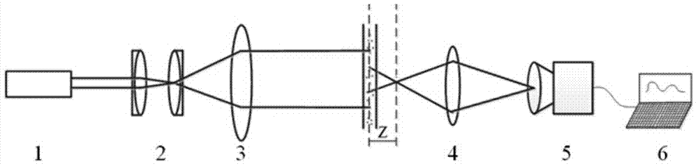
[0038] The working principle of the present invention: the laser emits a coherent beam, and through the spatial filter, most of the stray light generated by the laser is filtered out, and then the laser is collimated by the collimating lens, and the collimated beam irradiates the solution to be measured, due to the particles Scattering occurs due to existence, and then the focal length of the lens behind the measurement area is adjusted, so that the speckle image formed by the su...


PUM


Abstract

The invention discloses a flow two-dimensional velocity field measurement method and device based on near-field scattering, wherein the measurement device includes a laser, a spatial filter, a collimator lens, a lens group, a CCD camera and a computer, and Compared with the prior art, the present invention has the following advantages: the measuring device is quite simple, does not require high centering of the optical path, and can realize effective removal of stray light without adding a complex device for removing central light intensity; The particle size of the tracer particles required by the measurement technology can be smaller than the wavelength of the incident light emitted by the laser, and the concentration of the tracer particles can also be relatively high, which can be applied to the measurement of the two-dimensional velocity field of nanofluid flow; the data analysis of this measurement technology It is simple and fast, can realize online measurement, and adopts the differential processing method to ensure that the accuracy and linearity of the speed measurement method are not limited by the particle size and concentration of the tracer particles.

Description

technical field [0001] The invention belongs to the technical field of velocity measurement, and in particular relates to a method and device for measuring a flow two-dimensional velocity field based on near-field scattering. Background technique [0002] In modern fluid dynamics experiments, how to accurately, quickly and simply measure the flow field distribution of fluid flow has always been a very challenging problem in the field of velocity measurement. Usually, small tracer particles are added to the fluid, and the velocity distribution is measured by illuminating the fluid and detecting scattered light. At present, the common techniques for measuring two-dimensional velocity fields mainly include laser speckle velocimetry (LSV), particle image velocimetry (PIV) and holographic particle image velocimetry (HPIV) developed on the basis of LSV. [0003] Both LSV and PIV (HPIV) compare two frames of images with known time intervals, and use spatial cross-correlation metho...

Claims


Application Information

Patent Timeline
Patent Type & Authority Patents(China)
IPC IPC(8): G01P5/22
Inventor 许传龙谭浩张彪
Owner SOUTHEAST UNIV
Why Eureka
Try Eureka