
Multiple spark route for lightning protection

A spark gap and multiple technology, applied in the direction of spark gap, overvoltage arrester using spark gap, electrical components, etc., can solve the problems of assembly cost and limitation, and achieve simplified operation, reduced assembly cost, and reduced space requirements Effect

Inactive Publication Date: 2015-06-10
OBO BETTERMANN GMBH & CO KG
View PDF5 Cites 8 Cited by
  • Summary
  • Abstract
  • Description
  • Claims
  • Application Information

AI Technical Summary

Problems solved by technology

This means, for example, a non-negligible assembly effort for a triple arrangement in a network with three phase arresters or even a quadruple arrangement when additional protection between PE-N is to be realized.
Not only does this conventional arrangement result in additional assembly effort, but the arrangement also requires a corresponding installation space
Such installation space is usually limited in installation cabinets etc. where such spark gaps are to be provided

Method used


Image

  • Multiple spark route for lightning protection
  • Multiple spark route for lightning protection
  • Multiple spark route for lightning protection

Examples


Embodiment Construction

[0085] In the exemplary embodiment, a multipolar multiple spark gap for lightning protection is shown, which is combined in a single device. The important components of the design scheme are the following.

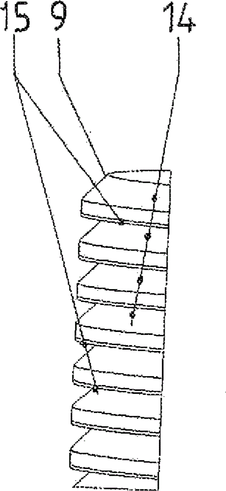
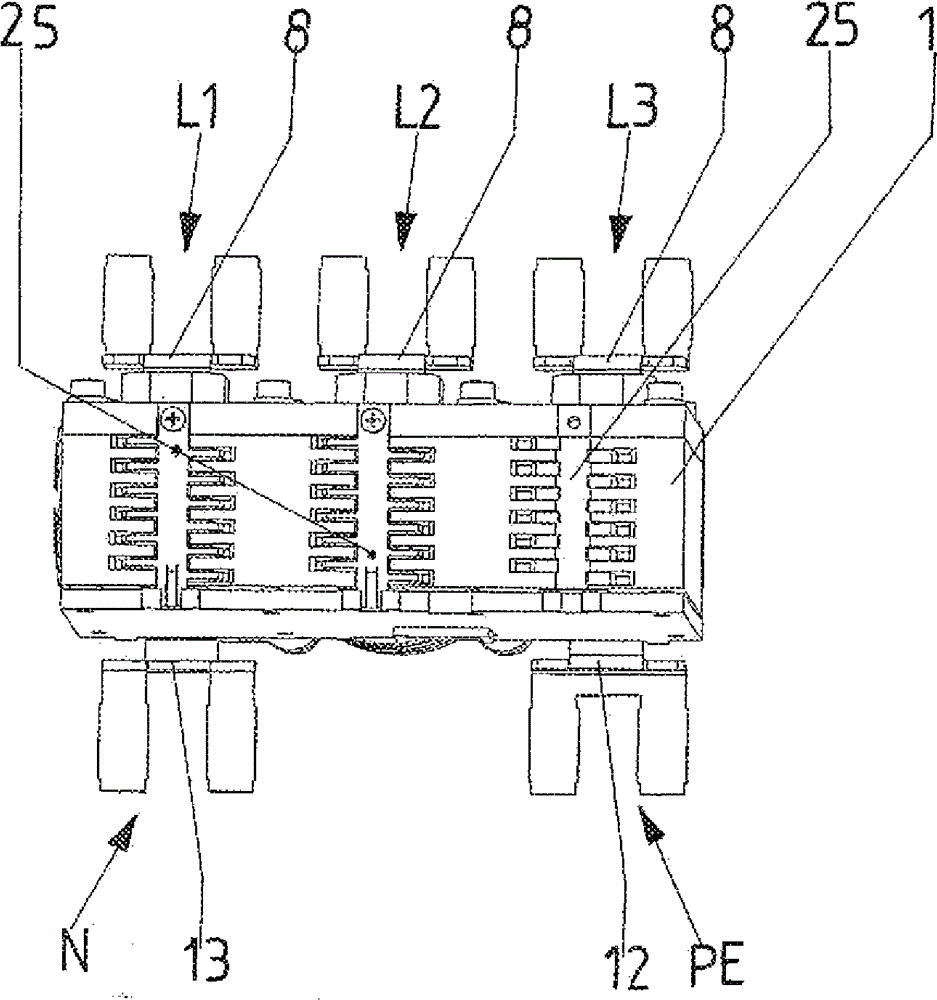
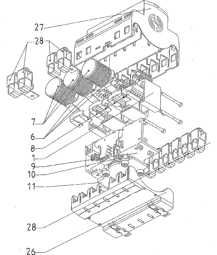
[0086] A housing 1 of insulating material, for example made of plastic, is provided which has a plurality of chambers 2 , 3 , 4 which are isolated from one another. especially by Image 6 It can be seen that the chambers 2 , 3 , 4 are designed in such a way that they exit openly towards the housing side. A coupling contact plate 6 is inserted into these cavities 2, 3, 4 adjacent to the housing bottom 5, respectively, on which is stacked a spark gap 7 in contact with it, which spark gap 7 is inserted into the corresponding cavity 2, 3, 4 . Each connecting contact plate 6 has a respective connecting piece 8 for an electrical conductor on a bent arm, wherein the connecting piece 8 is led out through the housing wall of the insulating material housing 1 towards its outer si...


PUM


Abstract

The invention relates to a multiple spark route for lightning protection composed of spark gaps arranged between connecting contact plates and contact plates with connecting members used for electric conductors. An insulation material housing (1) with a plurality of mutually isolated chambers (2, 3, 4) is arranged. The connecting contact plates (6) are inserted, and then the spark gaps (7) in contact with the spark gas are further inserted. The connecting members (8) respectively used for the electric conductors (8) are separately lead out of the outer side of the insulation material housing (1) through the housing body wall. An open side of the housing is covered by a first contact plate (9) made of conductive materials. The first contact plate (9) is in contact with the spark gaps (7) in a side, back on to the connecting contact plates, of the first contact plate. The first contact plate (9) is connected to the insulation material housing (1) through the connecting members. The first contact plate has the connecting members used for the electric conductors (8).

Description

technical field [0001] The invention relates to a multiple spark gap for lightning protection, comprising a spark gap arranged between a connection contact plate and a contact plate with a connection piece for an electrical conductor. Background technique [0002] A multiple spark gap is known from DE 2013 102 647 . As in the present invention, an electrode plate, preferably in the form of an annular graphite disk, is arranged there. The annular insulation here is preferably formed by an annular disk of polytetrafluoroethylene, as in the present invention. [0003] For the prior art reference is also made to document WO 2012 / 052388 A1. [0004] It has hitherto been common and necessary in the prior art to arrange such multiple spark gaps separately for each phase of the network and also to provide a corresponding spark gap between PE and neutral. This implies a non-negligible installation effort for a triple arrangement, for example in a network with three phase arresters...

Claims


Application Information

Patent Timeline
Patent Type & Authority Applications(China)
IPC IPC(8): H01T4/16H01T4/06
CPCH01T4/06H01T4/16
Inventor W.布赖特豪普特M.霍夫曼J.舒尔万茨
Owner OBO BETTERMANN GMBH & CO KG
Learn More