Multifunctional overcurrent clamp capable of being mounted vertically

A vertical installation, multi-functional technology, applied in the field of tools, can solve the problems that will affect other procedures, the insulation rod is not connected, the insulation rod cannot be disassembled, etc., to improve the range of operability, avoid dangerous factors, and light weight. Effect

Active Publication Date: 2015-06-10
LIAOYANG POWER SUPPLY COMPANY OF STATE GRID LIAONING ELECTRIC POWER SUPPLY +1
View PDF11 Cites 1 Cited by
  • Summary
  • Abstract
  • Description
  • Claims
  • Application Information

AI Technical Summary

Problems solved by technology

[0004] The first type can be installed on the slow arc downward drainage due to the tight connection with the insulating rod. The insulating rod cannot be disassembled, which will affect other procedures of the operation.
[0005] The overcurrent fixture of the second type of detachable insulating rod is not connected to the insulating rod. It is hung by the insulating rod and then locked, but it can only be hung on the horizontal wire, and it cannot be installed on the slow arc downward drainage.

Method used


Image

  • Multifunctional overcurrent clamp capable of being mounted vertically
  • Multifunctional overcurrent clamp capable of being mounted vertically
  • Multifunctional overcurrent clamp capable of being mounted vertically

Examples


Embodiment 1

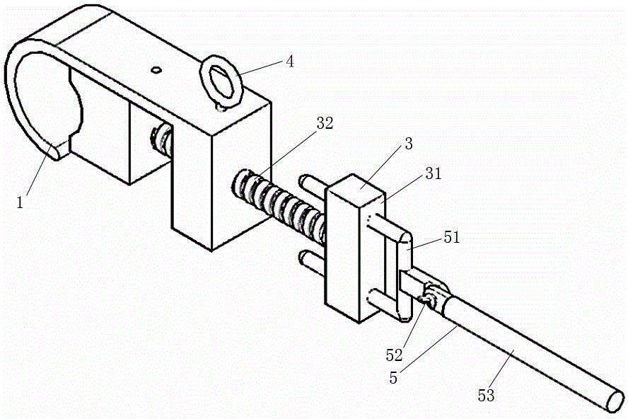
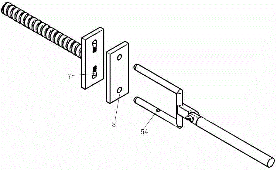
[0019] Such as figure 1 , 3 As shown, the multifunctional overcurrent fixture that can be installed vertically includes a wire clamping groove 1, a T-shaped installation head 3 and an insulating U-shaped installation rod 5. The T-shaped installation head 3 includes a locking screw 32 and an installation plate 31, the locking screw 32 is vertically installed in the middle of the mounting plate 31, and there are two through holes 8 on the mounting plate 31, and a touch bead 7 is respectively arranged at the middle position in each through hole, and on the wire card slot A screw hole is provided, and the locking lead screw is threadedly connected with the lead slot through the screw hole, and the two plugs of the insulating U-shaped mounting rod 5 are inserted in the through hole.

[0020] The insulating U-shaped installation rod 5 includes a U-shaped fork 51 and an insulating rod 53, the U-shaped fork and the insulating rod are connected by a butterfly buckle 52, the front end ...

Embodiment 2

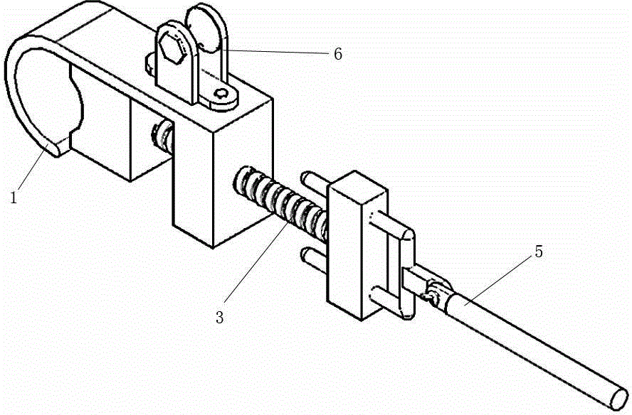
[0024] Such as figure 2 As shown, the flow pulley 6 is installed on the side wall of the wire clamping groove 1 described in this embodiment through the installation hole, and the rest is the same as that of the embodiment 1.

[0025] This embodiment is used on wires.


PUM


Abstract

The invention relates to a multifunctional overcurrent clamp capable of being mounted vertically. The multifunctional overcurrent clamp comprises a conductor clamping groove, a T-shaped mounting head and an insulated U-shaped mounting rod; the T-shaped mounting head comprises a locking lead screw and a mounting plate; the locking lead screw is vertically mounted in the middle of the mounting plate; two through grooves are formed in the mounting plate; a bead is arranged in each through hole; a screw hole is formed in the conductor clamping groove; the locking lead screw is connected with the conductor clamping groove by use of the screw hole; the two plugs of the insulating U-shaped mounting rod are inserted into the two through holes. The multifunctional overcurrent clamp is rotated by a worker on a tower to drive the conductor clamping groove to be tightened or untightened; when an overcurrent pulley is mounted on a horizontal live conductor, an arc extinction rope is used for short-circuiting the potential difference of drainage by use of the overcurrent pulley. The clamp can be applied to any towers and any conductors. The clamp is manufactured by use of a high-strength aluminum alloy, and has the characteristics of light weight, high strength, strong current conductivity and convenience for mounting.

Description

technical field [0001] The invention relates to a tool used for live operation of 220kV and 66kV transmission lines, in particular to a multifunctional overcurrent fixture which can be installed vertically. Background technique [0002] Since the drainage of the tension tower of the transmission line is an installation form of downward slow arc, it is necessary to short-circuit the live wires on both sides of the connecting plate with metal wires in the work of disconnection and drainage of the line on both sides of the connecting plate to ensure Before and after the plate is opened, the charged wires on both sides are always at the same potential, and there is no potential difference. The traditional method of live disconnection and drainage of transmission lines is to use equipotential electricians to enter a strong electric field and tie metal wires on the slow arc downward drainage for short-circuiting, so that the live wires on both sides are at the same potential, whic...

Claims


Application Information

Patent Timeline
Patent Type & Authority Applications(China)
IPC IPC(8): H02G7/08
CPCH02G1/02
Inventor 张森丁雷张烈然丁冠西董政曾海腾宋洁敏曲家波寿增尚勇周胜潘鹏飞张乐
Owner LIAOYANG POWER SUPPLY COMPANY OF STATE GRID LIAONING ELECTRIC POWER SUPPLY
Why Eureka
Try Eureka