
case

A shell and component technology, applied in the field of shells, can solve problems such as high cost, and achieve the effect of promoting production costs, low-cost manufacturing, and easy assembly

Inactive Publication Date: 2019-11-15
ROBERT BOSCH GMBH
View PDF5 Cites 0 Cited by
  • Summary
  • Abstract
  • Description
  • Claims
  • Application Information

AI Technical Summary

Problems solved by technology

[0005] Therefore, for solutions according to the prior art, for example, seals with specific dimensions are required or complex technical solutions

Method used


Image

  • case
  • case
  • case

Examples


Embodiment Construction

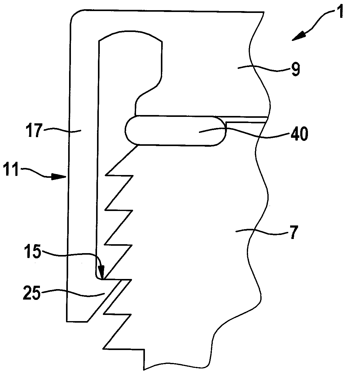
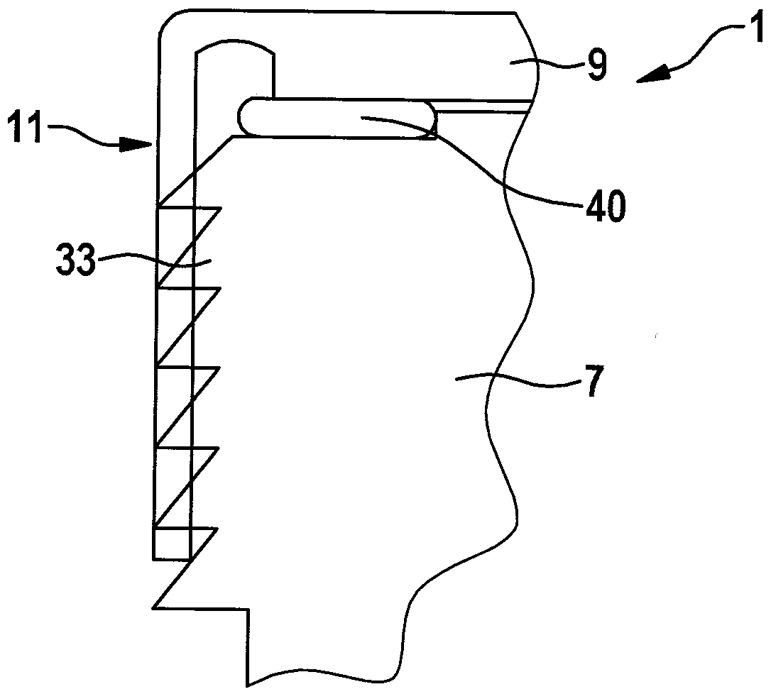
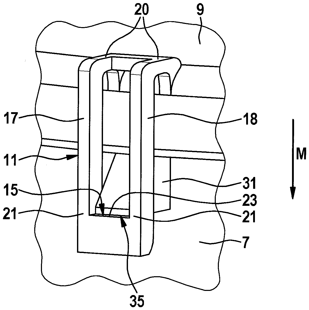
[0025] figure 1 A partial area of ​​a housing 5 with a snap-fit ​​connection, as is generally known in the prior art, is shown. The housing 5 comprises a first housing part 7 and a second housing part 9 . The first housing part 7 and the second housing part 9 are joined together in the assembly direction M to form the housing 5 . A snap clip 11 is attached to the second housing part 9 . The snap clip 11 comprises two snap tabs 17 , 18 which extend in the assembly direction M. As shown in FIG. The detent tongues 17 , 18 are connected at their first end 20 to the second housing part 9 . At their second end 21 , the detent tongues 17 , 18 are connected via a detent hoop bridge 23 . The locking clip bridge 23 extends perpendicularly to the assembly direction M. As shown in FIG. The detent bridge 23 has detent flanks 15 . The latching flank 15 is located between the two latching tongues 17 , 18 . The locking flanks 15 are flat surfaces. The latching flanks 15 extend perpend...


PUM


Abstract

The invention relates to a housing (5) provided with a first housing part (7) and a second housing part (9). The first or the second housing part (7, 9) is an electronic housing, in particular to an electromotor housing. Under the combined action of locking elements (33) of a locking part (31) connected with the first housing part (7) and a locking hoop (11) connected with the second housing part (9), the first housing part (7) and the second housing part (9) are maintained together. Therefore, the locking part comprises at least two locking elements (33).

Description

technical field [0001] The invention relates to a housing according to the class of the independent claim. Background technique [0002] A housing is known which has a first and a second housing part which are pressed together by a snap connection. Furthermore, it is known that a detent element of a detent connected to a first housing part interacts with a detent hoop connected to a second housing part and forms a snap connection. [0003] A pump consisting of a motor and a pump head is shown in DE 20 2004 013 907 U1. The pump head and motor are connected to each other by a snap connection. Each snap connection is formed by the interaction of a snap clip fastened on the motor via a snap flange and a snap lock on the pump head. Each of the locking parts includes a unique locking element. [0004] The pump shown in DE 36 03 812 A1 also has a snap-in connection, in particular a snap-in connection, for connecting the motor to the pump head. However, the snap-in connection h...

Claims


Application Information

Patent Timeline
Patent Type & Authority Patents(China)
IPC IPC(8): H05K5/00
CPCH05K5/0013
Inventor C.迈尔C.阿克
Owner ROBERT BOSCH GMBH
Learn More