Method for detecting a malfunction in a camshaft offset device

A technology of offset device and fault detection, applied in valve device, engine starting, electrical control and other directions, can solve the problem of inaccurate and reliable fault detection, and achieve the effect of reliable diagnosis

Active Publication Date: 2015-06-10
RENAULT SA
View PDF6 Cites 0 Cited by
  • Summary
  • Abstract
  • Description
  • Claims
  • Application Information

AI Technical Summary

Problems solved by technology

[0005] Today, the methods currently available do not detect such faults with sufficient accuracy and reliability for industrial applications

Method used


Image

  • Method for detecting a malfunction in a camshaft offset device
  • Method for detecting a malfunction in a camshaft offset device
  • Method for detecting a malfunction in a camshaft offset device

Examples


Embodiment Construction

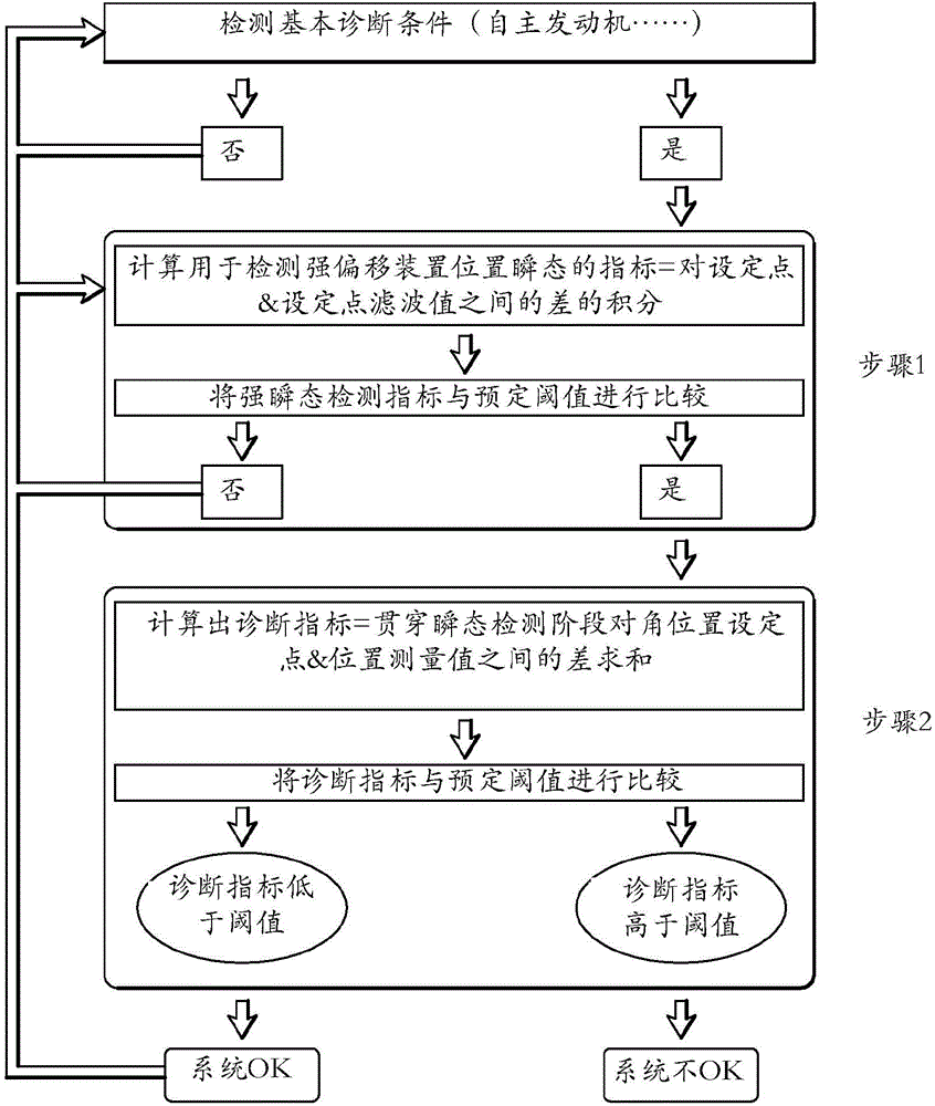
[0031] The method according to the invention is carried out automatically by means of a computer, for example the central processing unit of the motor vehicle. All steps of the method according to the invention are carried out systematically and automatically by this computer, without intervention of the driver of said vehicle.

[0032] see figure 1 , the method according to the invention comprises an initial step consisting in verifying that the engine of the vehicle is under standard operating conditions. In fact, if the engine has to function in extreme environments, for example at very high temperatures, there may be a risk that the results provided by the method according to the invention will not be reliable, not least because of the thermal expansion of the deflection means, This would unnaturally impair its operation and / or its control.

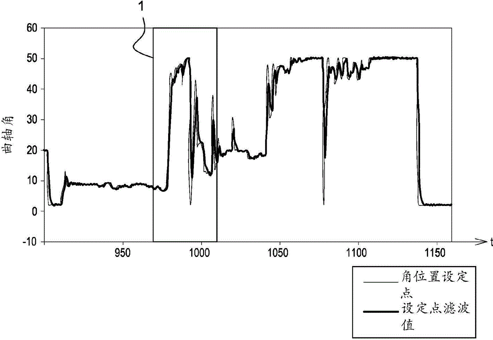
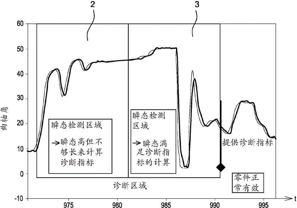
[0033] The method comprises a first step of identifying at least one potential diagnostic area which can be used as a basis for a...


PUM


Abstract

The invention relates to a method for detecting a malfunction in a camshaft offset device of a motor vehicle. The main characteristic of a method according to the invention is that it comprises the following steps: a step of checking the standard engine operation conditions; a step of identifying a diagnosis area (3, 5) corresponding to a transient phase affecting a given period; and a step of detecting a malfunction of the offset device in said diagnosis area (3, 5).

Description

technical field [0001] The object of the invention is a method for detecting faults in a camshaft offset device. Background technique [0002] Such an offset device corresponds to what is more generally known as a variable valve timing (VVT) device. [0003] So far, only important faults in the camshaft offset device, such as sticking in the protective position or the maximum position, for example, have been detected. On this subject, United States patent application US 20080011256 sets forth an engine management system that makes it possible to detect a malfunction of an offset device by comparing the two angular positions of the camshaft in a protected position in time. If the difference between these two positions meets or exceeds a threshold value, the offset device is considered defective. [0004] As anti-pollution regulations evolve, it becomes increasingly important to be able to detect more subtle faults in the camshaft offset system, such as too long a time betwe...

Claims


Application Information

Patent Timeline
Patent Type & Authority Applications(China)
IPC IPC(8): F01L1/344F02D41/22
CPCF01L1/344F01L2800/11F02D41/009F02D41/221F02D2200/701F02N2200/123Y02T10/40
Inventor N·图弗内尔J·米兰
Owner RENAULT SA
Why Eureka
Try Eureka