Filter assembly

A filter assembly and filter technology, which is applied in the direction of fixed filter elements, filter separation, chemical instruments and methods, etc., can solve the problems of increasing costs and achieve the effect of strong expansion ability

Active Publication Date: 2015-06-17
TENNECO SUZHOU EMISSION SYST
View PDF7 Cites 1 Cited by
  • Summary
  • Abstract
  • Description
  • Claims
  • Application Information

AI Technical Summary

Problems solved by technology

In addition, it is often necessary to design matching filters for different engine after-treatment systems. This solution requires designing different filters for different engine after-treatment systems, which greatly increases the cost

Method used


Image

  • Filter assembly
  • Filter assembly
  • Filter assembly

Examples


Embodiment Construction

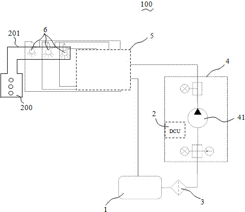
[0032] Please refer to figure 1 As shown, the present invention discloses an exhaust aftertreatment system 100 applicable to large engines, which includes a urea tank 1, a filter assembly 3 connected to the urea tank 1, and a fluid delivery system for delivering the urea solution device 4 , a common rail 5 connected to the fluid delivery device 4 , several nozzles 6 connected to the common rail 5 and a controller 2 for controlling the exhaust gas post-treatment system 100 .

[0033] In the illustrated embodiment of the present invention, the engine 200 is a high-power engine whose power generally exceeds 500 kilowatts. The fluid delivery device 4 is provided with a pump 41 (such as a gear pump, etc.) for pumping the urea solution. In the illustrated embodiment of the present invention, the controller 2 is installed on the fluid delivery device 4 to realize integration. The nozzle 6 is used to spray atomized urea solution into the engine exhaust pipe 201 . The atomized urea ...


PUM


Abstract

The invention discloses a filter assembly. The filter assembly comprises a first filter and a second filter, wherein the first filter comprises a first housing, a first filter element and a first head, wherein a first inlet channel and a first outlet channel are formed in the first head; the second filter comprises a second housing, a second filter element and a second head; a second inlet channel and a second outlet channel are formed in the second head; the first inlet channel is communicated with the second inlet channel; the first outlet channel is communicated with the second outlet channel; the first filter and the second filter are separately arranged and are detachably assembled together through a fixture; the fixture is used for detachably assembling the first head with the second head. By virtue of the arrangement, the systematic design is realized; a right number of filters are selected and integrated according to different application requirements.

Description

technical field [0001] The invention relates to a filter assembly, in particular to a filter assembly used in an engine exhaust aftertreatment system and used to filter urea solution. Background technique [0002] The current engine exhaust after-treatment system generally includes a urea tank, a urea pump for pumping the urea solution out of the urea tank, and a filter for filtering the urea solution. [0003] When the filter is used in a large engine aftertreatment system, in order to meet a certain filtering capacity, it is necessary to design a filter with a larger size. In addition, it is often necessary to design matching filters for different engine aftertreatment systems. This solution requires designing different filters for different engine aftertreatment systems, which greatly increases the cost. [0004] Therefore, it is necessary to design a new type of filter assembly based on combining several filters to solve the above problems. Contents of the invention ...

Claims


Application Information

Patent Timeline
Patent Type & Authority Applications(China)
IPC IPC(8): B01D53/92B01D35/02B01D29/33B01D29/56
CPCB01D29/33B01D29/56B01D35/02B01D53/92
Inventor 樊高峰
Owner TENNECO SUZHOU EMISSION SYST
Why Eureka
Try Eureka