Method for automatically unloading drill bit

An automatic unloading and drilling technology, which is applied to drilling/drilling equipment, components of boring machines/drilling machines, metal processing equipment, etc., can solve the problems of complex disassembly methods, complicated operations, time-consuming and labor-intensive

Inactive Publication Date: 2015-06-17
铜陵市永生机电制造有限责任公司
View PDF7 Cites 0 Cited by
  • Summary
  • Abstract
  • Description
  • Claims
  • Application Information

AI Technical Summary

Problems solved by technology

[0002] Rotor disassembly is a common industrial process. The current disassembly method is complicated, cumbersome, time-consuming and labor-intensive

Method used


Image

  • Method for automatically unloading drill bit

Examples


Embodiment Construction

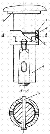
[0006] like figure 1 As shown, the operation steps of the present invention include: putting the ferrule 1 on the spindle 4 of the drilling machine, pushing it to the waist-shaped hole, inserting the cross pin 5 into the waist-shaped hole through the side hole of the ferrule, and the cross pin can be inserted into the waist-shaped hole. Slide up and down inside, the ferrule can slide on the drill spindle. In order to prevent the ferrule from falling off freely, a spring leaf 2 is clamped between the ferrule and the main shaft. When the main shaft is retracted upwards to a certain position after work, the ferrule collides with the fixed part 6 above, and the ferrule drives the cross pin to hit the tail end of the drill bit, and the drill bit is washed off from the taper hole of the main shaft.

[0007] By adopting the above steps, the disassembly process is simple and convenient, and the working hours are shortened.


PUM


Abstract

The invention discloses a method for automatically unloading a drill bit. The method comprises the following steps: a sleeve ring (1) coats a drilling machine main shaft (4), and is pushed to a waist hole; a transverse pin (5) is inserted into the waist hole through a side hole of the sleeve ring, and can vertically slide in the waist hole; and the sleeve ring can slide on the drilling machine main shaft. In order to prevent free drop of the sleeve ring, a spring piece (2) is clamped between the sleeve ring and the main shaft; and when the main shaft upwards shrinks to a certain position after the operation is finished, the sleeve ring touches a fixed part (6) on the upper surface, and drives the transverse pin to touch collide the tail end of the drill bit so as to flush off the drill bit from a conical hole of the main shaft. The method adopts the steps, so that the unloading process is simple and convenient, and the labor hour is shortened.

Description

technical field [0001] The invention relates to a mechanical disassembly method. Background technique [0002] Rotor disassembly is a common industrial process. The current disassembly method has complicated steps, cumbersome operations, and time-consuming and labor-intensive operations. Contents of the invention [0003] In order to solve the above-mentioned technical problems, the operation steps of the present invention include: putting the ferrule on the main shaft of the drilling machine, pushing it to the waist hole, inserting the cross pin into the waist hole through the side hole of the ferrule, and the cross pin can be inserted into the waist hole Slide up and down and the ferrule slides on the drill press spindle. In order to prevent the ferrule from falling off freely, a spring leaf is clamped between the ferrule and the main shaft. When the main shaft is retracted to a certain position after work, the ferrule collides with the fixed part above, and the fer...

Claims


Application Information

Patent Timeline
Patent Type & Authority Applications(China)
IPC IPC(8): B23B47/00
CPCB25B27/02
Inventor 朱俊生
Owner 铜陵市永生机电制造有限责任公司
Why Eureka
Try Eureka