A lever counterweight type gravity compensation device
What is Al technical title?
Al technical title is built by PatSnap Al team. It summarizes the technical point description of the patent document.
A technology of gravity compensation and counterweight, which is applied to the simulation device of space navigation conditions, transportation and packaging, space navigation equipment, etc., can solve the problems that the space cannot be expanded without gravity, and achieve a beautiful overall layout, smooth transition, Avoid the effect of collision impact
Inactive Publication Date: 2020-06-05
BEIHANG UNIV
View PDF7 Cites 0 Cited by
Summary
Abstract
Description
Claims
Application Information
AI Technical Summary
This helps you quickly interpret patents by identifying the three key elements:
Problems solved by technology
Method used
Benefits of technology
Problems solved by technology
[0005] The purpose of the present invention is to provide a gravity compensation that can offset the gravity of the antenna itself in order to solve the problem that the large-scale one-dimensional extended antenna equipment in space is bent and deformed due to its own gravity when the ground is horizontally deployed, and the state of space-free deployment cannot be realized. device
Method used
Image
Click on the blue label to locate the original text in one second.
Reading with bidirectional positioning of images and text.
Examples
Embodiment Construction
[0029] The present invention will be described in further detail below in conjunction with the accompanying drawings and specific examples, but the implementation of the present invention is not limited thereto.
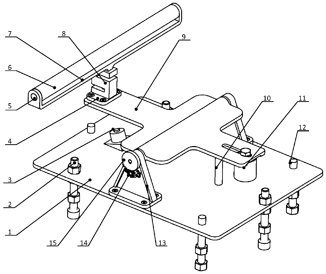
[0030] Such as figure 1 As shown, the present invention is a lever counterweight type gravity compensation device, which is characterized in that it includes a support assembly, a rotating plate assembly and a bottom plate assembly, wherein:
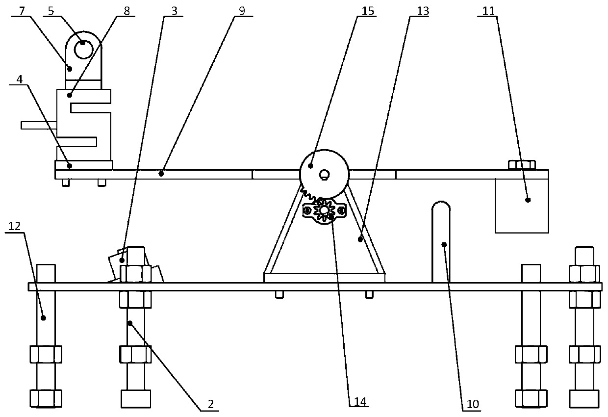
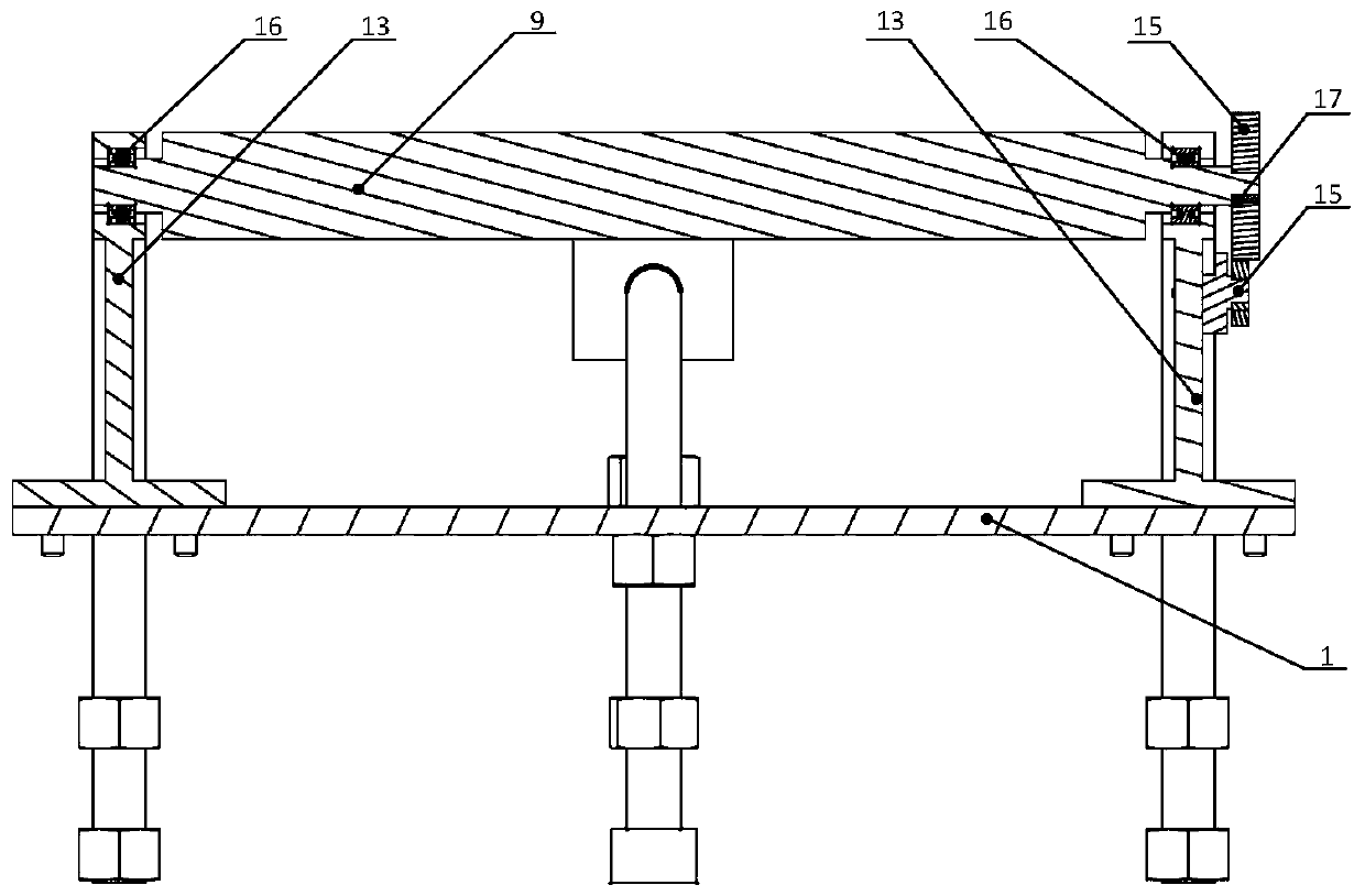
[0031] The support assembly is composed of an adapter 4, a rotating shaft 5, a plastic roller 6, a roller support 7, and a pressure sensor 8; the adapter 4 is used to connect the pressure sensor 8 and the rotating plate 9, and it is processed with four countersunk holes and middle One through hole, the through hole is used to connect the pressure sensor 8 through M3 bolts, and the four countersunk holes are used to connect the rotating plate 9 through four M4×10 bolts; the plastic roller is 280 long and the outer diameter t...
PUM
Abstract
The invention relates to a lever counter weight type gravity compensation device used for one-dimension deployed antenna ground deployment tests of spacecrafts such as satellites. The lever counter weight type gravity compensation device comprises a supporting assembly, a rotating plate assembly and a bottom plate assembly; the supporting assembly is composed of an adaptor, a rotating shaft, a plastic roller, a roller support, a pressure sensor and the like; the rotating plate assembly is composed of a rotating plate, a counter weight, rotating supports, a damper gear, an intermittent gear, bearings, a key and the like; the bottom plate assembly is composed of a bottom plate, bottom plate locking levers, sucked type electromagnets, a limiting pin, bottom plate guide rods and the like. When an antenna is deployed, the compensation device is in a sucked and combined state, and the sucked type electromagnets are powered on and sucked and combined with the rotating plate; after the antenna is deployed, the sucked type electromagnets are powered off, the rotating plate can rotate stably under the functions of the counter weight, the intermittent gear, the damper gear and the like, and finally the rotating plate supports the antenna to compensate the gravity. By means of the lever counter weight type gravity compensation device, the problem of gravity compensation of space antenna ground deployment tests is solved, the structure of the device is simple, the operation is convenient, the compensation force is adjustable, and no impact exists.
Description
technical field [0001] The invention relates to a lever counterweight type gravity compensation device, in particular to a set of devices capable of performing gravity compensation on a large one-dimensional extending antenna with variable diameter or fixed diameter, and displaying the compensation force in real time. Background technique [0002] Since the beginning of the 21st century, the aerospace industry of various countries has achieved rapid development, and the technology of space vehicles such as satellites has continued to improve. Large-scale one-dimensional extension antennas are an important component of various spacecraft. During the development process, the zero-gravity one-dimensional deployment test of the antenna is a An essential test content, so a set of gravity compensation device is needed to compensate the force to simulate the zero gravity environment. [0003] By reviewing the existing literature, it is found that the gravity compensation of the lar...
Claims
Application Information
Patent Timeline
Application Date:The date an application was filed.
Publication Date:The date a patent or application was officially published.
First Publication Date:The earliest publication date of a patent with the same application number.
Issue Date:Publication date of the patent grant document.
PCT Entry Date:The Entry date of PCT National Phase.
Estimated Expiry Date:The statutory expiry date of a patent right according to the Patent Law, and it is the longest term of protection that the patent right can achieve without the termination of the patent right due to other reasons(Term extension factor has been taken into account ).
Invalid Date:Actual expiry date is based on effective date or publication date of legal transaction data of invalid patent.