A Simple Lock Body Mechanism
What is Al technical title?
Al technical title is built by PatSnap Al team. It summarizes the technical point description of the patent document.
A lock body mechanism and simple technology, applied in the direction of building locks, building structure, construction, etc., can solve the problems of complex process, many accessories, and high cost, and achieve the effect of reducing the process, reducing the cost of raw materials, and reducing the opening process.
Inactive Publication Date: 2017-04-05
广西力保佳科技有限公司
View PDF5 Cites 0 Cited by
Summary
Abstract
Description
Claims
Application Information
AI Technical Summary
This helps you quickly interpret patents by identifying the three key elements:
Problems solved by technology
Method used
Benefits of technology
Problems solved by technology
[0003] To sum up, the current ordinary indoor door lock body has many and complex accessories, and the upper and lower covers of the lock body need to be perforated, the process is complicated and the cost is high
Method used
Image
Click on the blue label to locate the original text in one second.
Reading with bidirectional positioning of images and text.
Examples
Embodiment Construction
[0049] Now in conjunction with accompanying drawing, the present invention is described in detail:
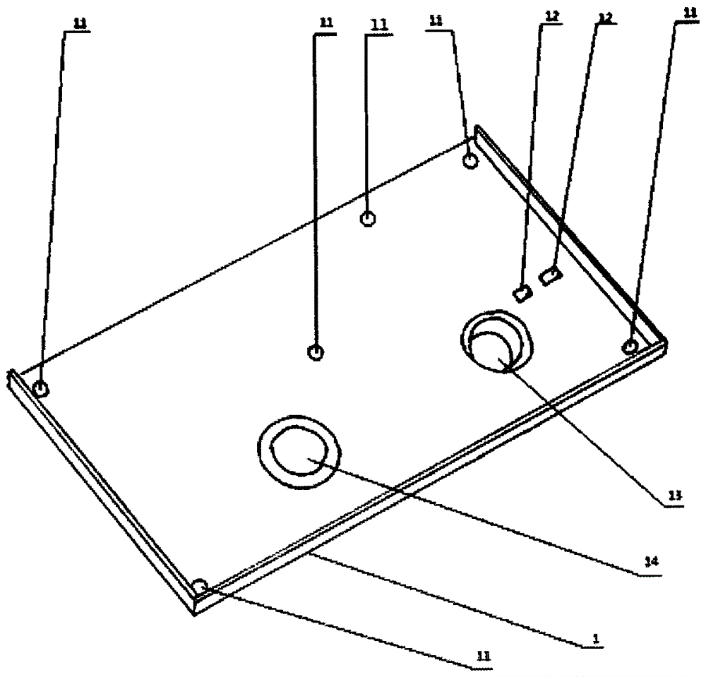
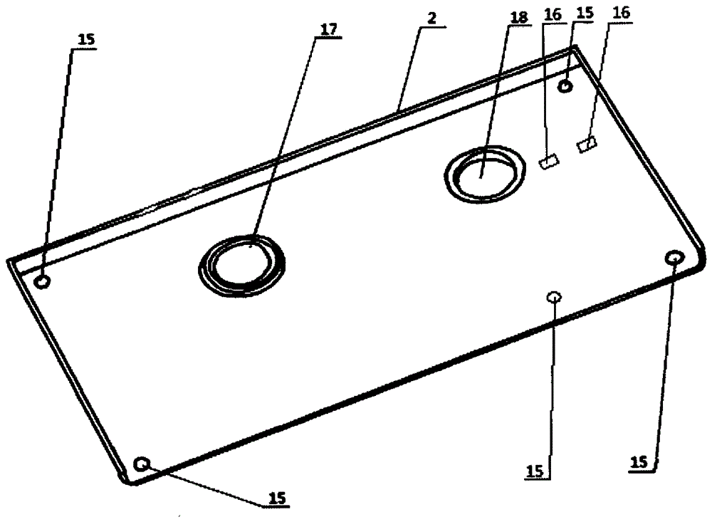
[0050] The present invention is composed of base (1), loam cake (2), lock body panel (3), oblique lock piece (4), reverse bolt (5), powder-ink metallurgy (6), square hole shift fork (7), U-shaped seat (8), square hole shift fork control frame (9), connecting rod fixed seat frame (10) is formed.
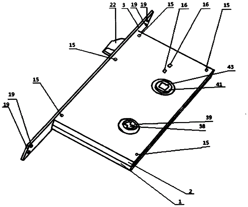
[0051] figure 1 Shown is the structural representation of the present invention. Wherein, 1 is the base (1), 2 is the loam cake (2), 3 is the lock body panel (3), 15 is the screw hole two (15) that is provided with on the loam cake top plate, and 16 is on the loam cake top plate The fixed seat hole two (16) that is provided with on the top, 19 is the screw hole three (19) that is provided with on the lock body panel, and 22 is oblique deadbolt (22), and 38 is that set in the middle of guide post one. The square bar jack (38) that has, 39 is movable post one (39), and 41 is guide pos...
PUM
Abstract
The invention discloses a simple lock body mechanism. The mechanism is composed of a base, an upper cover, a lock body front panel, an oblique locking component, a back locking tongue, powder metal, a square-hole shifting fork, a U-shaped seat, a square-hole shifting fork control frame and a connecting rod fixing seat frame. According to the simple lock body mechanism, seven components such as a lock cylinder, a main lock tongue base, a main lock tongue sliding block and a main lock tongue are removed, and a main lock tongue mechanism is removed, so that holes formed in the front panel for the main lock tongue are also eliminated. Meanwhile, the specifications of the base and the upper cover of the simple lock body mechanism are one third smaller than those of a common lock body, and the holes formed in the base and the upper cover are much fewer than those in the common lock body. In addition, according to the simple lock body mechanism, the lock cylinder does not need to be installed on a lock body. The formed lock body of the simple mechanism achieves the same function as an indoor door lock. Compared with the common lock body, the specifications of the upper cover and a lower cover are smaller than dimensions of those of the common indoor door lock body, and the procedures for opening holes in the upper cover and the lower cover are substantially reduced, so that the time for machining a finished product is shortened. The procedures are reduced, the cost of raw materials is greatly reduced, the manual machining cost is reduced, and the working benefits are increased.
Description
technical field [0001] The invention belongs to a door lock accessory, in particular to a simple lock body mechanism. Background technique [0002] The lock body is an important part of the door lock. Ordinary indoor lock body is composed of upper cover, lower cover, panel, oblique lock, reverse bolt, powder ink metallurgy, lock core, square hole shift fork, U-shaped seat, square hole shift fork control frame, connecting rod fixing seat, The main bolt base, the main bolt slider, the main bolt, the lock cylinder connecting rod, the lock cylinder fixing screw, the sky and the earth ditch and many other components. [0003] To sum up, the current ordinary indoor door lock body has many and complicated accessories, and the upper and lower covers of the lock body need to be perforated, which is complicated and costly. [0004] The specifications of the upper and lower covers of the current common door lock body are: length 178.6mm, width 99mm. In addition, an additional lock c...
Claims
Application Information
Patent Timeline
Application Date:The date an application was filed.
Publication Date:The date a patent or application was officially published.
First Publication Date:The earliest publication date of a patent with the same application number.
Issue Date:Publication date of the patent grant document.
PCT Entry Date:The Entry date of PCT National Phase.
Estimated Expiry Date:The statutory expiry date of a patent right according to the Patent Law, and it is the longest term of protection that the patent right can achieve without the termination of the patent right due to other reasons(Term extension factor has been taken into account ).
Invalid Date:Actual expiry date is based on effective date or publication date of legal transaction data of invalid patent.