Regular-triangular-arrayed vortex array heat-transfer device

An equilateral triangle heat exchange device technology, applied in the field of vortex-row array heat exchange devices, can solve the problems of unresearched heat transfer vortex rotation direction, fluid flow momentum and energy loss, heat transfer coefficient reduction, etc., to achieve convenient design Effect of layout and fabrication, reduced flow resistance, high heat transfer coefficient

Inactive Publication Date: 2015-06-17
SOUTHEAST UNIV
View PDF7 Cites 1 Cited by
  • Summary
  • Abstract
  • Description
  • Claims
  • Application Information

AI Technical Summary

Problems solved by technology

[0003] The heat transfer vortex array heat exchange devices commonly used at present are all parallel vortex schemes, that is, the vortex directions of all heat transfer vortexes are the same, and the direction of rotation is the same for the fluid separated in the tube, but for the fluid surrounding the tube, Since the flow direction of the fluid in the helical channel at the tangent point of two adjacent heat transfer vortices arranged along the vortex is opposite, the formed convective flow will inevitably lead to the loss of fluid flow momentum and energy, which will eventually cause heat transfer. Decrease in coefficient or increase in flow resistance
Although there are applications of reverse scrolls in mechanical occasions such as twin-screw compressors or oil pumps, it is a pity that in the field of heat transfer, there has not been any relevant research on the role of the direction of rotation of the heat transfer scroll in the heat transfer scroll array at home and abroad. research or make effective use of

Method used


Image

  • Regular-triangular-arrayed vortex array heat-transfer device
  • Regular-triangular-arrayed vortex array heat-transfer device
  • Regular-triangular-arrayed vortex array heat-transfer device

Examples


Embodiment Construction

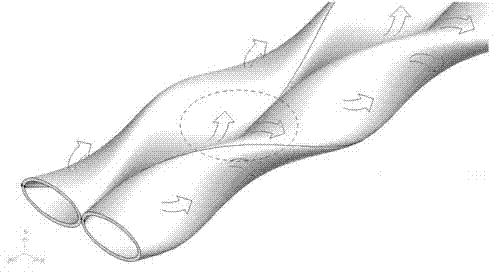
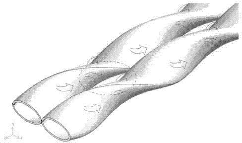
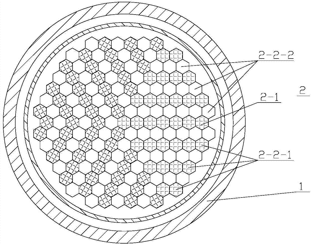
[0017] A paired vortex-row array heat exchange device arranged in an equilateral triangle, comprising a cylindrical shell 1, and a heat transfer core 2 is arranged inside the cylindrical shell 1; it is characterized in that the heat transfer core 2 includes Y-shaped vortex arrangement (that is, adjacent heat transfer vortex bodies have the same vortex direction) Y-shaped heat transfer vortex body row 2-1; the center of the Y-shaped heat transfer vortex body row 2-1 is located in the cylindrical shell 1 center point, and the included angle between two adjacent arms of the Y shape is 120°; a heat transfer vortex array 2-2 is arranged in each sector formed by the adjacent two arms of the Y shape, and the The thermal vortex array 2-2 is composed of a right-handed V-shaped heat transfer vortex row 2-2-1 and a left-handed V-shaped heat transfer vortex row 2-2-2 arranged in a V-shaped vortex. The angle between the two arms of the left-handed V-shaped heat transfer vortex row is 120°;...


PUM


Abstract

The invention relates to a regular-triangular-arrayed vortex array heat-transfer device. The regular-triangular-arrayed vortexes array heat-transfer device comprises a cylindrical shell and a heat-transfer core body; the heat transfer core body comprises Y-shaped heat-transfer vortex arrays arrayed along the vortexes; a heat-transfer vortex array formed by rotate-right or rotate-left V-shaped heat-transfer vortexes is arranged in each sector area formed by two Y-shaped adjacent arms; the rotation direction of the Y-shaped heat-transfer vortexes arrays is opposite to the rotation direction of adjacent V-shaped heat-transfer vortexes arrays, and the rotation directions of the heat-transfer vortexes in two adjacent rows of V-shaped heat-transfer vortex arrays are opposite. The regular-triangular-arrayed vortex array heat-transfer device has the advantages that the flow directions in a channel at the tangent position of the adjacent heat-transfer vortex arrays is the same, improving of the heat-transfer effect is facilitated, the flow resistance is reduced, and the cost is nearly increased; the regular-triangular-arrayed vortex array heat-transfer device can be used in the occasions of a twisted ellipse tube heat exchanger, nuclear reactor core and the like.

Description

technical field [0001] The invention relates to a vortex array heat exchange device, in particular to a paired vortex row array heat exchange device arranged in an equilateral triangle. Background technique [0002] Vortex flow is a phenomenon that exists in nature. Because its main flow basically does not change direction, the flow resistance is relatively small. There are many examples of the application of spiral vortex in the field of enhanced heat transfer technology, such as twisted elliptical tube heat exchangers, threaded grooved tube heat exchangers and spiral baffle heat exchangers. [0003] The heat transfer vortex array heat exchange devices commonly used at present are all parallel vortex schemes, that is, the vortex directions of all heat transfer vortexes are the same, and the direction of rotation is the same for the fluid separated in the tube, but for the fluid surrounding the tube, Since the flow direction of the fluid in the helical channel at the tangen...

Claims


Application Information

Patent Timeline
Patent Type & Authority Applications(China)
IPC IPC(8): F28F13/12
Inventor 陈亚平巨福军吴嘉峰
Owner SOUTHEAST UNIV
Why Eureka
Try Eureka