Method and device for testing gas content of shale gas reservoir

A technology for shale gas reservoirs and testing devices, which is applied in the direction of analyzing materials and instruments, can solve the problems of large gas loss errors, cannot fully characterize the effect of water saturation on adsorbed gas, etc., and achieves a high degree of automation and automatic data monitoring. Effect

Active Publication Date: 2015-06-17
CHINA PETROLEUM & CHEM CORP +1
View PDF5 Cites 44 Cited by
  • Summary
  • Abstract
  • Description
  • Claims
  • Application Information

AI Technical Summary

Problems solved by technology

[0004] Desorption method is used to measure shale gas content. The measurement results are easily affected by factors such as coring method, measurement method, calculation method of gas loss, accuracy of measuring reservoir gas content (desorbed gas, residual gas), gas desorption temperature, etc., and the gas loss can be calculated. big error
The current tests of shale adsorption capacity refer to the experimental technical standards of coalbed methane adsorption capacity, using pulverized shale particles and ignoring the influence of pore structure, let alone fully characterizing the effect of water saturation on adsorbed gas

Method used


Image

  • Method and device for testing gas content of shale gas reservoir
  • Method and device for testing gas content of shale gas reservoir
  • Method and device for testing gas content of shale gas reservoir

Examples


Embodiment Construction

[0027] In order to make the object, technical solution and advantages of the present invention more clear, the present invention will be further described in detail below in conjunction with the examples. It should be understood that the specific embodiments described here are only used to explain the present invention, not to limit the present invention.

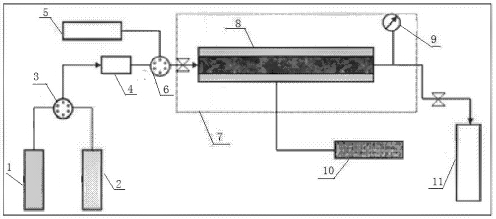
[0028] Such as figure 1 As shown, the shale gas reservoir gas content test device includes a high-pressure nitrogen gas inlet device 1, a high-pressure natural gas inlet device 2, a first six-way valve 3, a booster pump 4, an evacuation device 5, a second six-way valve 6, Constant temperature box 7, core desorption flow model 8, pressure sensor 9, ring pressure control pump 10 and gas metering device 11;

[0029] The high-pressure nitrogen inlet device 1 and the high-pressure natural gas inlet device 2 are connected to the second six-way valve 6 after passing through the first six-way valve 3 and the booster pump 4 through...


PUM

PropertyMeasurementUnit
particle diameteraaaaaaaaaa

Abstract

The invention discloses a method and device for testing the gas content of a shale gas reservoir. The device for testing the gas content of the shale gas reservoir comprises a high-pressure nitrogen inlet device, a high-pressure natural gas inlet device, a first six-way valve, a booster pump, a second six-way valve, an evacuator, a thermostat, a rock core desorption flow model, a pressure sensor, a ring crush control pump and a gas metering device, wherein the high-pressure nitrogen inlet device and the high-pressure natural gas inlet device are connected with the second six-way valve by virtue of pipelines after passing through the first six-way valve and the booster pump; the evacuator is connected with the second six-way valve; the second six-way valve is connected with the gas metering device by virtue of a pipeline after pasting through the rock core desorption flow model arranged in the thermostat; and the rock core desorption flow model is respectively connected with the pressure sensor and the ring crush control pump which is used for performing follow-up control on the ambient pressure of the rock core desorption flow model. By adopting the device disclosed by the invention, the shale gas desorption in the development process of a gas reservoir is researched by virtue of a physical simulation method, and the gas production rate during shale gas exploitation is measured.

Description

technical field [0001] The invention relates to the technical field of shale gas development, in particular to a method and device for testing the gas content of shale gas reservoirs. Background technique [0002] At present, the determination methods of shale gas content can be divided into two categories: direct method (desorption method) and indirect method (isothermal adsorption experiment method). The desorption method is the most direct method to measure the gas content of shale. The actual gas content is determined by using on-site drilling cores and representative cuttings. The measurement of shale gas content includes lost gas, desorbed gas and residual gas. Lost gas refers to the gas desorbed from the rock during the period from when the rock is lifted from the ground to when it is sealed in the tank, which cannot be measured. Calculating the lost gas is the key to accurately predict the gas content of shale; Desorption is measured with a burette; residual gas...

Claims


Application Information

Patent Timeline
Patent Type & Authority Applications(China)
IPC IPC(8): G01N7/14
Inventor 杨文新赵江艳苟群芳冯建芳
Owner CHINA PETROLEUM & CHEM CORP
Why Eureka
Try Eureka