Electrical contactor

An electrical contactor, delay time technology, applied in relays, electrical switches, electromagnetic relays, etc., can solve problems such as increased chattering, inability to overcome opening and closing contacts, and unbalanced contact drivers.

Inactive Publication Date: 2015-06-17
JOHNSON ELECTRIC SHENZHEN
View PDF7 Cites 0 Cited by
  • Summary
  • Abstract
  • Description
  • Claims
  • Application Information

AI Technical Summary

Problems solved by technology

However, this does not overcome the consequent problem of synchronously driving the movable arms or blades to open and close the contacts
This will cause a series of unbalance problems of the contacts and the driver, and even cause vibration and increase the vibration of the contacts

Method used


Image

  • Electrical contactor
  • Electrical contactor
  • Electrical contactor

Examples


Embodiment Construction

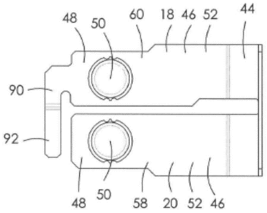
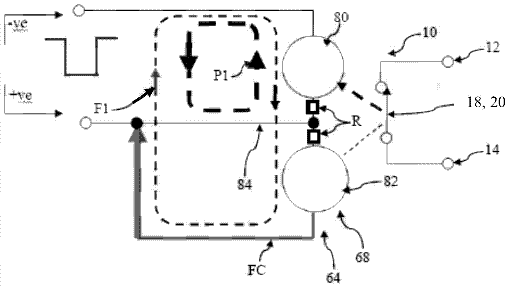
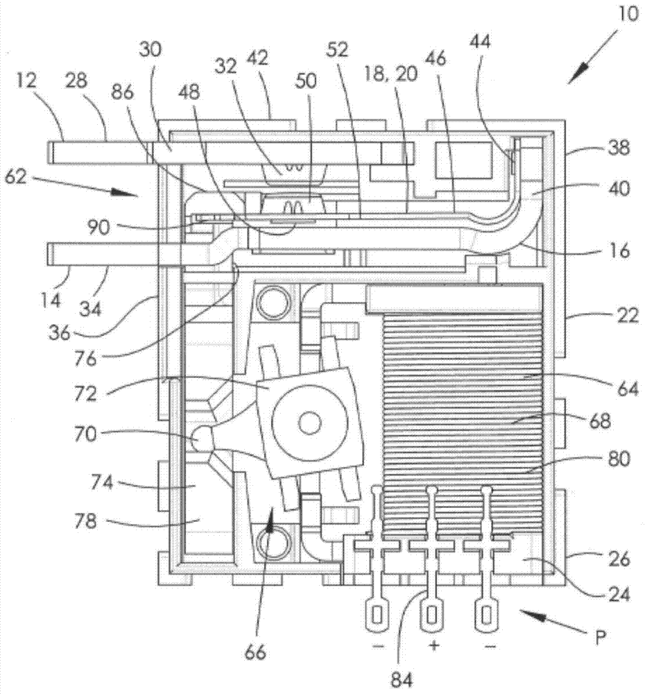
[0031] See first Figure 1 to Figure 7 , shows the first embodiment of the electrical contactor 10 of the present invention, which is a single-stage structure, including a first terminal 12 , a second terminal 14 , a bus bar 16 , and two movable arms 18 , 20 . In this embodiment, the booms 18 and 20 are installed on the busbar 16 .

[0032] The first and second terminals 12 , 14 protrude from the housing 22 of the contactor and are installed on the base plate 24 or the side wall 26 of the housing 22 . The cover on the housing base 22 is not shown in the figure, so as to clearly show the internal structure of the electrical contactor 10 .

[0033] The first terminal 12 includes a first pad 28 and a fixing part 30 , the fixing part 30 is preferably conductive, and extends from the first pad 28 into the housing 22 . At least one fixed contact 32 is disposed at or near the end of the fixing member 30 . In this embodiment, there are two fixed contacts 32 . Although the two fixe...


PUM


Abstract

An electrical contactor (10) comprises a first terminal (12) having a fixed member (30) with at least one fixed electrical contact (32), a second terminal (14), and at least one movable electrical contact (50) in electrical communication with the second terminal (14). A dual-coil actuator (64) is also provided and has a first drive coil (80) drivable to open and close the movable and fixed electrical contacts, and a second non-drive coil (82) feedback connected to induce a reverse flux to temper and stabilise a nett flux. Control of a delay time of the opening and closing electrical contacts is thus possible, so as to be at or adjacent to a subsequent or next zero-crossing of an associated AC load current waveform. A method of controlling electrical contact closing and opening delay, and a method of limiting or preventing electrical contact bounce and arc duration are also provided.

Description

technical field [0001] The present invention relates to electrical contactors, especially but not limited to coil-driven DC switch contactors applied to modern electric meters, that is, "smart electric meters", under normal domestic mains power supply, usually 100-250V alternating current, with Function of load disconnection protection. [0002] The invention also relates to an electrical contactor for a medium-current direct current switch, the contacts of which will not be welded in the event of a short-circuit fault. In the case of contact fusion during a short-circuit fault, the output current cannot be measured. If the load that should be disconnected is still connected to the 230V AC, it may cause a fatal electric shock. [0003] The term "medium current" means current less than or equal to 120Amps. [0004] In addition, it is also required to accurately control the opening and closing time of the contacts of the medium current switch, so as to reduce or avoid arc disc...

Claims


Application Information

Patent Timeline
Patent Type & Authority Applications(China)
IPC IPC(8): H01H50/86H01H50/58
CPCH01H50/58H01H50/86H01H47/18H01H47/226H01H50/24H01H50/44H01H50/642H01H51/2227H01H51/2272H01H7/16
Inventor 理查德·安东尼·康奈尔
Owner JOHNSON ELECTRIC SHENZHEN
Why Eureka
Try Eureka