Reference signal transmitting method and device

A reference signal and signal technology, applied in the directions of space transmit diversity, pilot signal allocation, transmission path sub-channel allocation, etc., can solve the problems of low effective transmission efficiency and increased overhead of Massive antenna arrays

Inactive Publication Date: 2015-06-17
ZTE CORP
View PDF4 Cites 6 Cited by
  • Summary
  • Abstract
  • Description
  • Claims
  • Application Information

AI Technical Summary

Problems solved by technology

Obviously, a large increase in the number of transmitting antennas will inevitably lead to a sharp increase in the overhead of reference signals used

Method used


Image

  • Reference signal transmitting method and device
  • Reference signal transmitting method and device
  • Reference signal transmitting method and device

Examples


no. 1 example

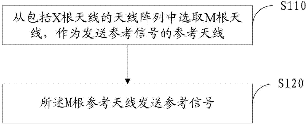
[0061] Such as figure 1 As shown, this embodiment provides a method for transmitting a reference signal, and the method includes:

[0062]Step S110: Select M antennas from the antenna array including X antennas as reference antennas for sending reference signals; the M is smaller than X, and the M reference antennas are scattered in the antenna array;

[0063] Step S120: the M reference antennas transmit reference signals.

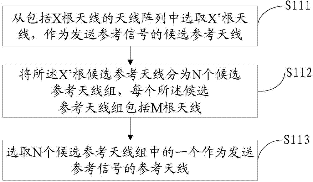
[0064] The antenna array described in step S110 may be a Massive antenna array, and X antennas are arranged in rows and / or columns. The M reference antennas are scattered in the antenna array, and the M antennas are sparsely distributed in the antenna array. specific as figure 2 As shown, if the antenna array includes 32 antennas and is divided into 4 rows and 8 columns. Select 8 antennas as reference antennas, and the selected 8 antennas are not concentrated distribution, but scattered in different rows and different columns, and there is at least on...

example 1

[0086] Example 1, assuming that the number of candidate reference antennas X' is equal to the product of the number of candidate reference antenna groups N and the number of antennas M included in each group, specifically: assuming X'=32, N=4 and M=8, it is possible to form The following defined groupings:

[0087] The first group: 5,10,13,20,22,24,27,31;

[0088] The second group: 3,7,9,11,17,23,25,32;

[0089] The third group: 1,6,12,14,16,18,28,30;

[0090] The fourth group: 2,4,8,15,19,21,26,29.

example 2

[0091] Example 2, assuming that the number of candidate reference antennas X' is less than the product of the number of candidate reference antenna groups N and the number of antennas M included in each group, specifically: assuming X'=32, N=4 and M=10, it is possible to form The following groupings are identified:

[0092] The first group: 1,5,10,13,17,20,22,24,27,31;

[0093] The second group: 3,7,9,11,15,17,23,25,28,32;

[0094] The third group: 1,6,12,14,16,18,21,26,28,30;

[0095] The fourth group: 2,4,8,11,15,19,21,24,26,29.

[0096] In the above example 2, different candidate reference antenna groups include at least one same antenna, that is, the antennas included in different candidate reference antenna groups are the same; for example, the first and second candidate reference antenna groups both include candidate reference antennas. Antenna 17, the second and fourth candidate reference antenna groups both include candidate reference antennas 11 and 15.

[0097] I...


PUM


Abstract

A reference signal transmission method, a device and a computer storage medium, pertaining to reference signal transmission technology in the field of wireless communications. The present reference signal transmission method comprises selection of a number M of antennae in an antenna array of a number X of antennae to serve as reference antennae for the transmission of a reference signal, and transmission by said number M of antennae of a reference signal, said number M being smaller than said number X, and said number M of antennae being distributed within said antenna array.

Description

technical field [0001] The present invention relates to a reference signal transmission technology in the field of wireless communication, in particular to a reference signal transmission method and device. Background technique [0002] In order to improve the spectrum efficiency and power efficiency in wireless communication, improve system capacity and coverage, the Massive antenna array technology based on large-dimensional antenna arrangement is introduced, so that the wireless resources of space can be deeply excavated and utilized, and the system can be significantly improved in theory. Spectral efficiency and power efficiency. However, Massive antenna array transmission will present some new characteristics, such as: the channel will have obvious sparsity in spatial distribution; the large array beam can almost completely eliminate the influence of noise, but the co-channel interference caused by pilot pollution will become a constraint system major factor in perform...

Claims


Application Information

Patent Timeline
IPC IPC(8): H04B7/04H04B7/06
CPCH04B7/0691H04L5/0023H04L5/0048H04B7/0608
Inventor 陈宪明李新彩鲁照华孙云锋陈艺戬
Owner ZTE CORP
Why Eureka
Try Eureka