Positioning mechanism
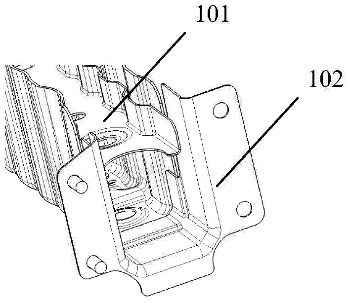
A technology of positioning mechanism and limit block, which is applied in auxiliary devices, vehicle components, auxiliary welding equipment, etc., can solve problems such as positioning difficult parts 101, achieve fast and accurate positioning, overcome difficult positioning, and improve welding efficiency Effect
- Summary
- Abstract
- Description
- Claims
- Application Information
AI Technical Summary
Problems solved by technology
Method used
Image

Examples
Embodiment Construction
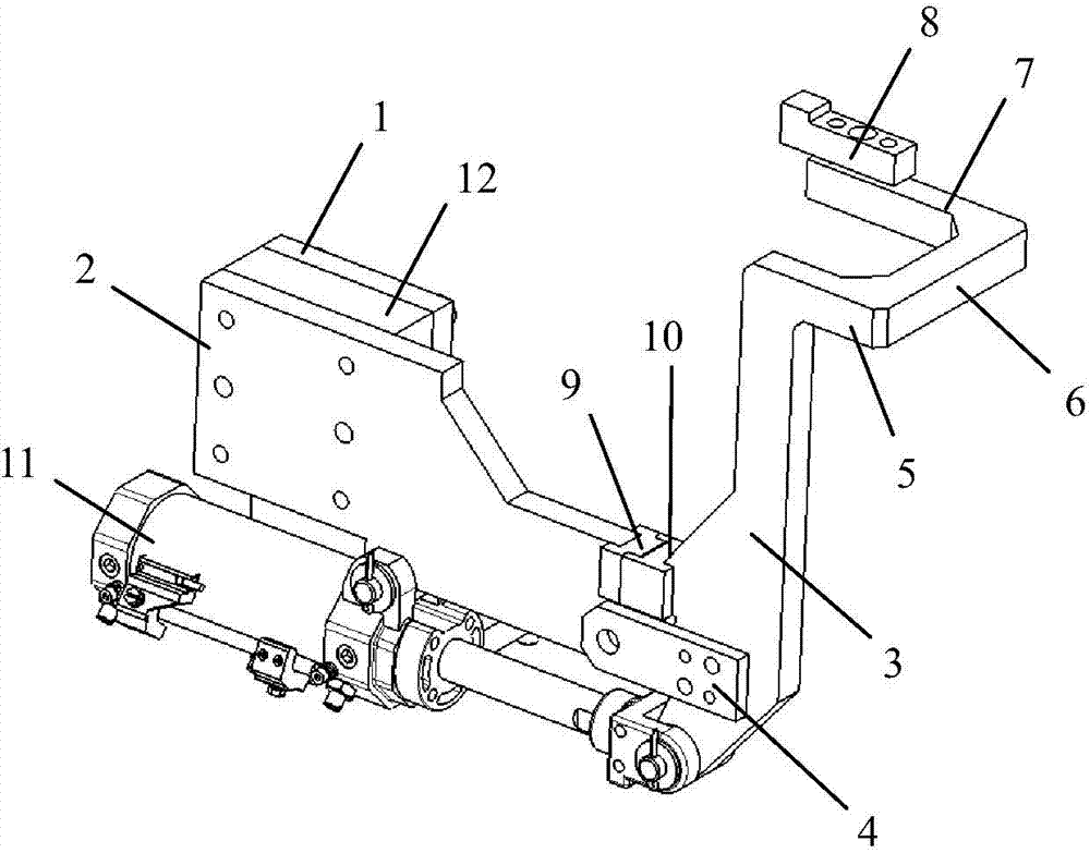
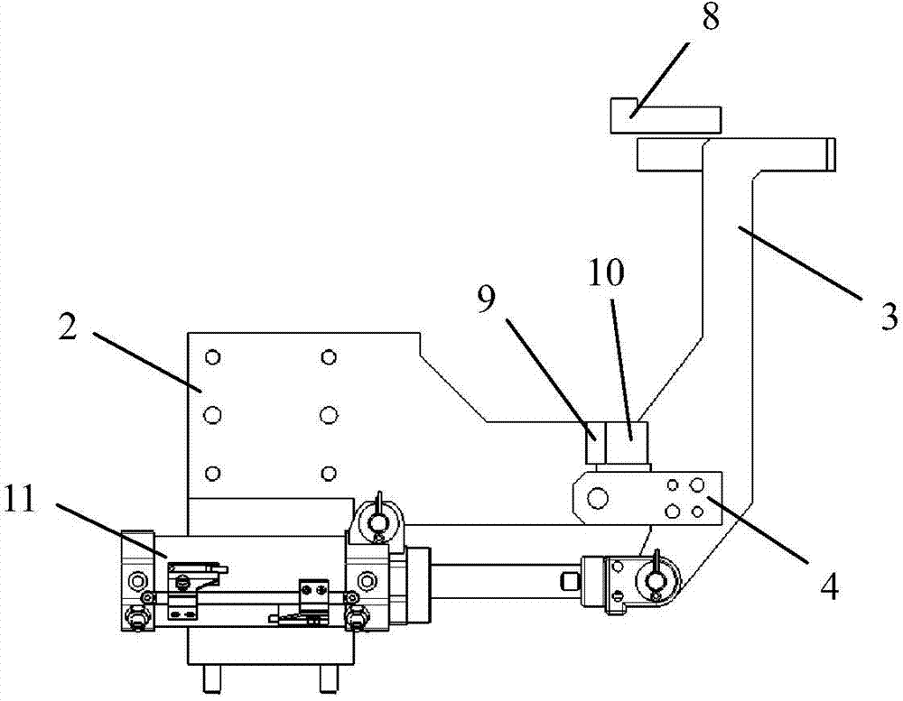
[0031] Below in conjunction with accompanying drawing and specific embodiment the present invention is described in further detail:
[0032] Such as figure 2 with image 3 As shown, a positioning mechanism includes a base 1, a mounting plate 2, a rotating plate 3, an adapter frame 4, a first rod 5, a second rod 6, a third rod 7, a support block 8 and a driving device. Wherein, one end of the mounting plate 2 is fixedly installed on one side of the upper end of the base 1 through bolt connection. The driving device can be a cylinder or a hydraulic cylinder. In this embodiment, the driving device is a cylinder 11. The free end of the piston rod in the cylinder 11 is hinged with one end of the rotating plate 3. For ease of installation, the piston in the cylinder 11 The free end of the rod is fixed with a U-shaped frame, and the end of the rotating plate 3 is hinged in the U-shaped groove of the U-shaped frame. In order to prevent interference during rotation, the gap between ...
PUM
 Abstract
Description
Claims
Application Information
PatSnap Eureka turns technology decisions into work you can execute. Powered by our Innovation Knowledge Graph, it runs expert workflows across engineering, life sciences, materials and intellectual property. Get your review-ready output in minutes.


