False twist texturing fancy yarn machine and processing method thereof
A technology of false twist deformation and fancy yarn, which is applied in the direction of spinning machine, continuous winding spinning machine, yarn, etc. It can solve the problems of affecting the quality of covered yarn, increasing the production process, and unable to realize continuous production, etc., and achieves The effect of stable speed, low carrying weight and improved quality
- Summary
- Abstract
- Description
- Claims
- Application Information
AI Technical Summary
Problems solved by technology
Method used
Image
Examples
Embodiment 1
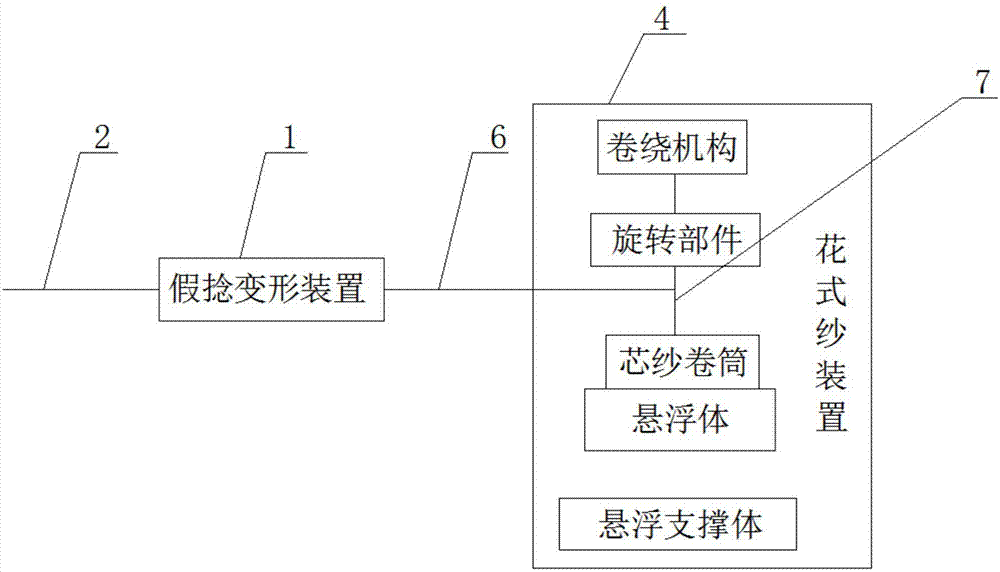
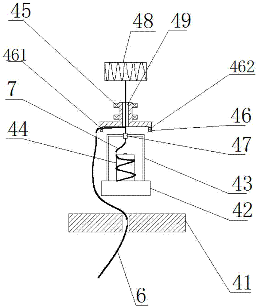
[0023] Such as figure 1 , figure 2 As shown, a false twist textured fancy yarn machine includes the following structures:
[0024] The false-twisting texturing device 1 is used for false-twisting and texturing the original yarn 2, and the elastic yarn obtained after the false-twisting texturing is the covering yarn 6. Under the traction of the traction mechanism of the false twist deformation device 1, the raw silk 2 is processed into elastic yarn mainly through its deformation heating box, false twister and other mechanisms, and the elastic yarn enters the fancy yarn device as the outer covering yarn 6 It is used to process covered yarn in the future; among them, the deformation heat box of the false twist deformation device 1 is used to heat the raw silk 2 to make it in a plasticized state and reduce its tensile deformation ability; the false twister generates mechanical twisting stress for False-twist deformation treatment is performed on the heated and plasticized raw y...
Embodiment 2
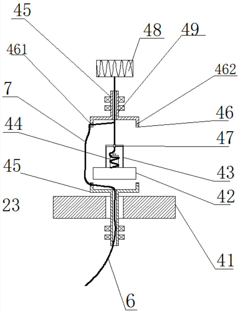
[0040]On the basis of Embodiment 1, in order to further assist the delivery and stable direction of the covering yarn 6 drawn from the false twist texturing device, a rotating part is added to the fancy yarn device 4 . image 3 As shown, a rotating part is added between the suspension body 42 and the suspension support body 41 to pass through the through hole arranged on the suspension support body 41, which is opposite to the rotation part above the installation frame 43, and the outer covering yarn 6 can be moved along the bottom The central hole 49 and the guide wire hole 461 of the rotating part penetrate into the guide wire hole 461 of the upper rotating part, rotate under the drive of the two rotating parts, and wrap between the upper rotating part and the mounting frame 43, and then the upper rotating part The central hole 49 of the rotating part is output.
Embodiment 3
[0042] As another suspension method, the suspension support body 41 is located on the side of the suspension body 42 to make it in a suspended state, Figure 4 As shown, the mounting frame 43 is fixed on the upper and lower ends of the suspension body 42, and the core yarn reel 44 is arranged on the mounting frame 43 in the space formed by the mounting frame 43 and the suspension body 42. The core yarn 7 passes through the tensioner on the mounting frame 43. 47 passes through the central hole 49 of the rotating part and is connected to the winding mechanism 48. After passing through the guide wire hole 461, the outer covering yarn 6 covers the core yarn 7 under the drive of the rotating part to form a covering yarn, and then is wound up by the winding mechanism 48. output.
PUM
 Abstract
Description
Claims
Application Information
 - R&D
- Intellectual Property
- Life Sciences
- Materials
- Tech Scout
- Unparalleled Data Quality
- Higher Quality Content
- 60% Fewer Hallucinations
Browse by: Latest US Patents, China's latest patents, Technical Efficacy Thesaurus, Application Domain, Technology Topic, Popular Technical Reports.
© 2025 PatSnap. All rights reserved.Legal|Privacy policy|Modern Slavery Act Transparency Statement|Sitemap|About US| Contact US: help@patsnap.com


