Pile foundation defect detection and repair method for cast-in-situ bored pile

A technique for bored cast-in-place piles and defects, which is applied in the repair of foundation structures, sheet pile walls, foundation structure engineering, etc., and can solve problems such as inability to determine broken piles or holes, poor detection results, and missed inspections of holes

Active Publication Date: 2015-06-24
NINGBO INST OF TECH ZHEJIANG UNIV ZHEJIANG
View PDF7 Cites 14 Cited by
  • Summary
  • Abstract
  • Description
  • Claims
  • Application Information

AI Technical Summary

Problems solved by technology

[0004] The method for detecting pile foundations in the prior art has the following disadvantages: 1. This method is particularly easy to miss holes, because the area of ​​the induction probe is small, and the range of the pile foundation signal actually collected is only the point where the probe is located vertically downward. For the convenience of expression, this line is called the sampling vertical line. If the hole is exactly on the sampling vertical line, it can be detected. However, in most cases, the hole is not located on the sampling vertical line, so there is no way to perceive it. In fact, the The method is only relatively sure for the detection of broken piles

Method used


Image

  • Pile foundation defect detection and repair method for cast-in-situ bored pile
  • Pile foundation defect detection and repair method for cast-in-situ bored pile
  • Pile foundation defect detection and repair method for cast-in-situ bored pile

Examples


Embodiment Construction

[0024] The present invention will be further described below in conjunction with the accompanying drawings and specific embodiments.

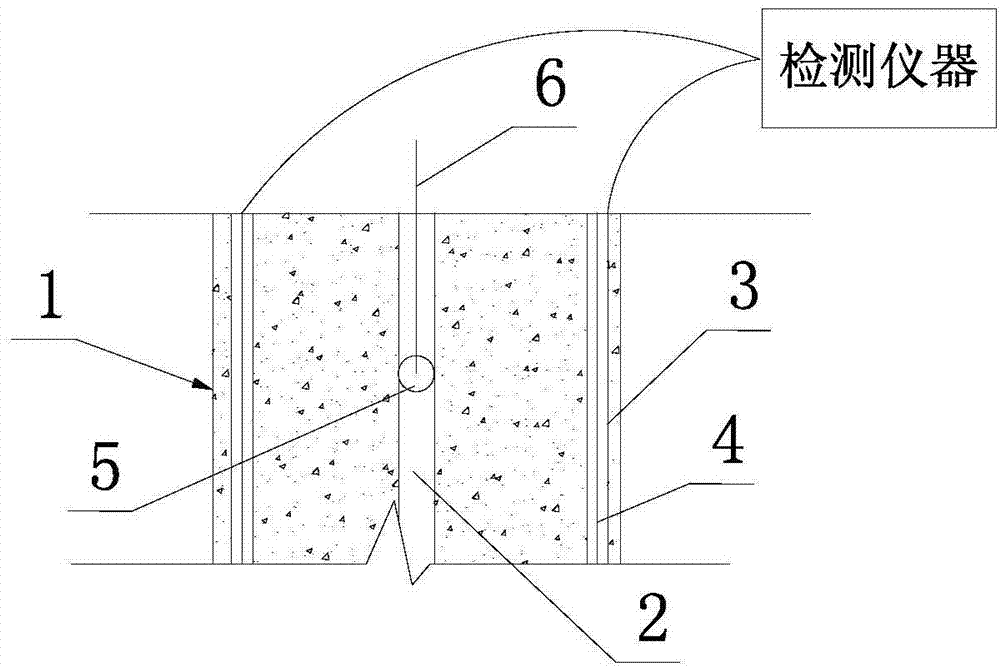
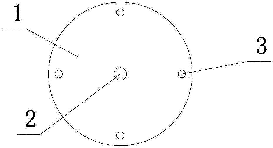
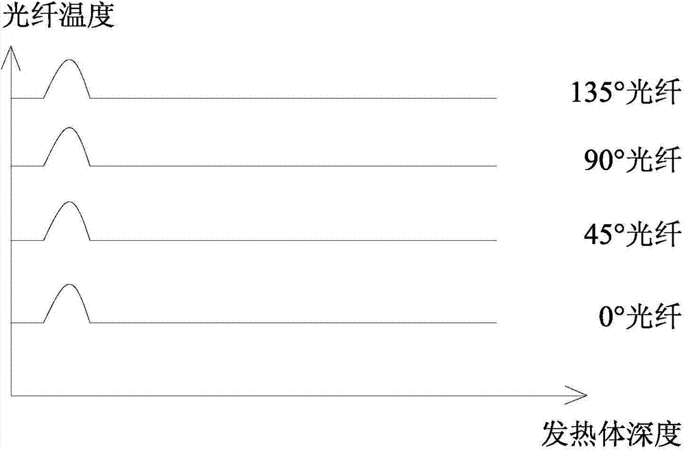
[0025] Such as figure 1 , figure 2 , image 3 , Figure 4 , Figure 5 As shown, the detection and repair method of the pile foundation defect of the bored pile of the present invention, its steps are as follows.

[0026] a. When pouring bored piles, reserve a central vertical hole 2 and several edge vertical holes 3, all edge vertical holes 3 are located on the same circumference and are evenly distributed along the circumferential direction, the central vertical hole 2 and edge vertical holes 3 all run through the whole pile body 1. When pouring bored piles, a plurality of vertical sleeves are pre-embedded, and then pulled out after pouring to form each edge vertical hole 3 and central vertical hole 2 . In this embodiment, four edge vertical holes 3 are provided, and their circumferential positions are respectively 0°, 45°, 90° and 135°...


PUM


Abstract

The invention discloses a pile foundation defect detection and repair method for a cast-in-situ bored pile. The method comprises the key steps that when a heating element (5) is located at a certain depth, if the waveform peak value of only one thermal inductance optical fiber (4) declines, it is judged that a cavity is formed in a pile body (1) at the depth, and the cavity is located at the position, passing through the radius of the abnormal thermal inductance optical fiber (4), of the cross section of the pile body (1); when the heating element (5) is located at a certain depth, if the waveform peak values of two adjacent thermal inductance optical fibers (4) decline, it is judged that the cavity is formed in the pile body (1) at the depth, and the cavity is located on a sector face formed by two radii passing through the two abnormal thermal inductance optical fibers (4); when the heating element (5) is located at a certain depth, if the waveform peak values of all thermal inductance optical fibers (4) decline, then it is judged that pile breaking exists at the depth. By means of the method, no missing detection is caused, the longitudinal depth of a broken pile at each layer can be detected accurately, the longitudinal depth of each cavity and the transverse locations, located on the cross section of a pile foundation, of the cavities can be detected, and effective repair can further be conducted on each defect.

Description

technical field [0001] The invention relates to the field of health monitoring of bored cast-in-situ piles in civil engineering, in particular to a method for detecting and repairing pile foundation defects of bored cast-in-situ piles. Background technique [0002] Due to the unfavorable factors such as high noise and environmental impact of piling, bored piles are generally used in urban construction with dense buildings. However, the quality of bored piles is affected by factors such as geographical environment, mechanical equipment, and human misoperation, which are prone to pile foundation defects, that is, broken piles or holes in the pile foundation concrete. [0003] In the prior art, the low-strain stress wave method is generally used to detect pile foundation defects. This detection method is based on the theory of elastic reflection. , to generate a stress wave that propagates vertically in the pile body. When there is a defect in the pile body, such as when the s...

Claims


Application Information

Patent Timeline
IPC IPC(8): E02D33/00E02D37/00E02D5/64
Inventor 毛江鸿金伟良杨劲秋李金柱方鹏飞王小军谢新宇李舒灵
Owner NINGBO INST OF TECH ZHEJIANG UNIV ZHEJIANG
Why Eureka
Try Eureka