Supercharge Your Innovation With Domain-Expert AI Agents!

Gripper assembly and lock/release method for a coiled tubing injector

A technology of oil pipe injection head and clamping device, which is applied in the direction of drilling equipment and methods, drilling pipes, casings, etc., to achieve the effects of cost and time saving, easy maintenance and replacement, and easy implementation

Inactive Publication Date: 2015-06-24
CHRIS MECHANICAL SERVICES
View PDF15 Cites 2 Cited by
  • Summary
  • Abstract
  • Description
  • Claims
  • Application Information

AI Technical Summary

Problems solved by technology

[0009] Although various improvements have been made to the clamping device for ease of installation and removal in operation, much time and expense are still required

Method used


Image

  • Gripper assembly and lock/release method for a coiled tubing injector
  • Gripper assembly and lock/release method for a coiled tubing injector
  • Gripper assembly and lock/release method for a coiled tubing injector

Examples


Embodiment Construction

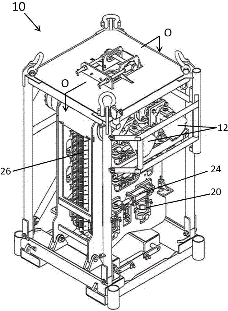
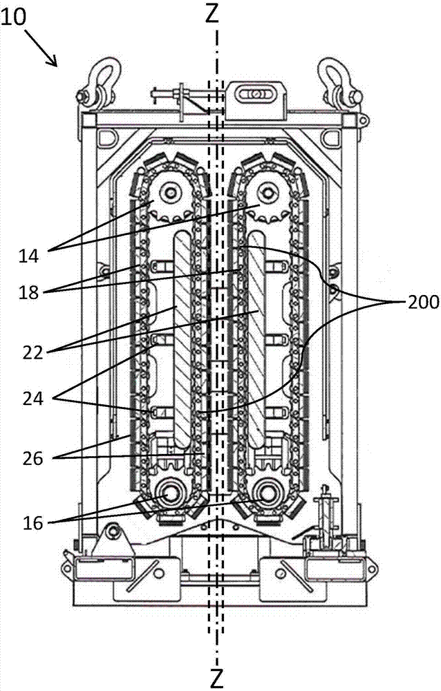
[0055] Attached below figure 2 Turning to FIG. 14 , a first embodiment of a gripping device for a typical coiled tubing injection head is shown, which is used to engage and grip coiled tubing for delivering or withdrawing a continuous length of coiled tubing into a well. like Figure 1B and 2 As shown, a plurality of clamping devices 100 , 100 . Each clamping device 100 is driven by a corresponding chain 200 and together with another opposing clamping device 100 driven by a corresponding chain 200 clamps and encases the coiled tubing therein.

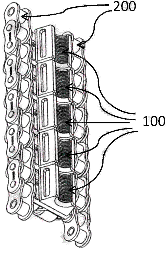
[0056] figure 2 A linear section of a conventional endless chain 200 with a gripping device 100 installed is shown in . see image 3 , a separate holding device 100 and its associated elements are mounted on the chain 200 . Chain 200 generally includes an inner chain plate 202 , an outer chain plate 204 , pins 206 and chain rollers 208 .

[0057] like Figure 4 As shown, in the first embodiment, the clamping device 100 include...


PUM


Abstract

A gripper assembly for a coiled tubing injector, each assembly of a plurality of assemblies having a carrier adapted for mounting to the injector drive and a gripper block releasably connected to the carrier using a locking mechanism. In an embodiment a locking tab extending from one of the gripper block and carrier engages a slot of the other of the carrier or block. A locking shaft extends through the assembly to engage the locking tab and releaseably lock the block to the carrier. The locking shaft is rotatable between a locking position to engage the locking tab to prevent release from the slot and a release position to release the locking tab from the slot. The shaft is biased to the locking position.

Description

technical field [0001] The present invention generally relates to a coiled tubing injection head, a clamping device for a coiled tubing injection head and a method of locking / dismounting the clamping device. Background technique [0002] As we all know, coiled tubing injection heads are widely used in the oil and gas industry to transport coiled tubing in and out of wells to perform various downhole operations such as remedial services, drilling, completions and production. As one of the important parts of the coiled tubing injection head, the clamping device is used to engage and clamp the coiled tubing to force a continuous length of coiled tubing into or out of an oil or gas well. [0003] Typically, the injector head is supported on cradles on the well. A continuous length of tubing is wound and supported on a drum and delivered to the injector head via an arcuate guide or commonly known as a "gooseneck". The injection head clamps the coiled tubing by means of clamping...

Claims


Application Information

Patent Timeline
IPC IPC(8): E21B19/22
CPCE21B19/22
Inventor 吉姆·希奇
Owner CHRIS MECHANICAL SERVICES
Features
  • R&D
  • Intellectual Property
  • Life Sciences
  • Materials
  • Tech Scout
  • Unparalleled Data Quality
  • Higher Quality Content
  • 60% Fewer Hallucinations
Learn More