Arc surface universal diaphragm coupling
A diaphragm coupling and curved surface technology, which is applied in the direction of couplings, elastic couplings, mechanical equipment, etc., can solve the problems of short service life and other problems, and achieve improved service life, economic benefits, and good flexible connection performance effect
- Summary
- Abstract
- Description
- Claims
- Application Information
AI Technical Summary
Problems solved by technology
Method used
Image
Examples
Embodiment 1
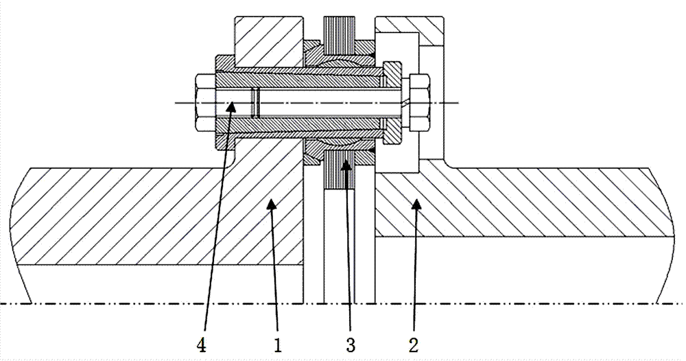
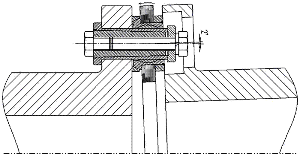
[0029] Arc surface universal diaphragm coupling, such as figure 1 and figure 2 As shown, it includes the driving flange 1, the driven flange 2, the diaphragm group 3 located between the driving flange 1 and the driven flange 2, and the diaphragm group 3, the driving flange 1 and the driven flange 2 and an expansion joint assembly 4 that is fixed as one; the diaphragm group 3 is connected as a whole through the diaphragm group arc surface movable sleeve assembly, and the expansion joint assembly 4 runs through the diaphragm group arc surface movable sleeve assembly Connect with driving flange 1 and driven flange 2.
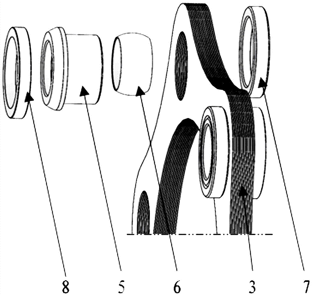
[0030] The cambered movable sleeve assembly of the diaphragm group is composed of a cambered sleeve 5 penetrating through the diaphragm set 3 , and a cambered collar 6 arranged in the cambered sleeve 5 and connected with the expansion joint assembly 4 .
[0031] In the present invention, the function of the expansion joint assembly 4 is to transition fit with th...
Embodiment 2
[0036] The difference between this embodiment and Embodiment 1 is that in order to achieve a better stable installation effect, such as figure 2 As shown, the movable sleeve component of the diaphragm group arc is also provided with a rivet ring 7 and an arc pad 8, and the specific setting method is as follows:
[0037] One side of the cambered movable sleeve assembly of the diaphragm group is provided with a riveting ring 7 that cooperates with the cambered sleeve 5 to compress the diaphragm group 3; through the cooperation of the riveting ring, multiple sheets of the same thickness can be effectively The film sheet is pressed and welded as a whole. The other side of the movable sleeve assembly with arcuate surface of the diaphragm set is provided with an arcuate surface pad 8 .
Embodiment 3
[0039] The difference between this embodiment and embodiment 1 or embodiment 2 is that, as figure 2 and Figure 4 As shown, the structure of the expansion joint assembly 4 in this embodiment is different, and the specific structure of the expansion joint assembly 4 in this embodiment is as follows:
[0040] The expansion joint assembly 4 consists of an expansion sleeve 41 with a tapered hole inside, a tapered sleeve 42 arranged in the expansion sleeve 41 and matched with the taper of the tapered hole, and a tension bolt 44 installed at the smaller end of the tapered sleeve 42 composition.
[0041] The installation steps of the expansion joint assembly 4 in the present embodiment are as follows:
[0042] After the flange and the diaphragm group are assembled, install the expansion sleeve from the reamed hole of the flange into the clearance fit, and then put the smaller end of the taper sleeve into the expansion sleeve to realize the gap between the expansion sleeve and the ...
PUM
 Abstract
Description
Claims
Application Information
 - R&D
- Intellectual Property
- Life Sciences
- Materials
- Tech Scout
- Unparalleled Data Quality
- Higher Quality Content
- 60% Fewer Hallucinations
Browse by: Latest US Patents, China's latest patents, Technical Efficacy Thesaurus, Application Domain, Technology Topic, Popular Technical Reports.
© 2025 PatSnap. All rights reserved.Legal|Privacy policy|Modern Slavery Act Transparency Statement|Sitemap|About US| Contact US: help@patsnap.com


