Method for operating a coriolis mass flowmeter

A mass flow and Coriolis technology, applied in mass flow measurement devices, direct mass flow meters, measuring flow/mass flow, etc., can solve the problem that sensor-assisted methods and methods cannot detect, cannot install sensors, and cannot simply Describe issues such as the effect of temperature gradients on the sensitivity and zero point of Coriolis mass flow meters

Active Publication Date: 2015-06-24
KROHNE MESSTECHNICK GMBH & CO KG
View PDF7 Cites 5 Cited by
  • Summary
  • Abstract
  • Description
  • Claims
  • Application Information

AI Technical Summary

Problems solved by technology

[0012] Unfortunately, sensor-assisted means and methods cannot detect and completely suppress all influences in the above-mentioned interference variables, because on the one hand it is not possible to install sensors that contribute to all interference variables and on the other hand it is not completely known. The functional relationship between the lateral sensitivity and the measured parameter can either not be described and / or calculated mathematically at an affordable cost
For example, the effect of a temperature gradient on the sensitivity and zero point of a Coriolis mass flow meter cannot be simply described

Method used


Image

  • Method for operating a coriolis mass flowmeter
  • Method for operating a coriolis mass flowmeter
  • Method for operating a coriolis mass flowmeter

Examples


Embodiment Construction

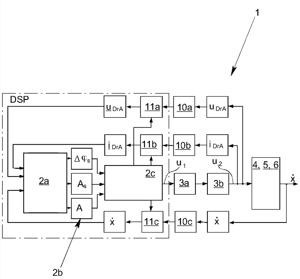
[0025] exist figure 1 1 first schematically shows a Coriolis mass flowmeter 1 with a regulator 2 implemented in a digital signal processor, an electrical servo 3 and an electrical drive 4 as a vibration generator. The electrical servo 3 generates an electrical excitation signal u for exciting the electrical drive 4 2 , wherein the electrical drive 4 excites the measuring tube 5 to vibrate in the first natural mode. The excited vibrations of the measuring tube 5 are detected by the vibration receiver 6 as a vibration measurement variable, wherein the measurement tube velocity is firstly detected as the vibration measurement variable . The temporal phase difference, ie the time offset (Zeitversatz) Δ, is then determined as a derived vibration measurement variable from the measuring tube velocities on the input and output sides. t .

[0026] exist figure 1 The Coriolis mass flowmeter 1 is shown in two parts. One half of the Coriolis mass flowmeter 1 actually forming a unit...


PUM


Abstract

A method for operating a Coriolis mass flowmeter in which the interferences when calculating the medium parameters is considered by the eigenfrequency (f01) of the oscillation of the measuring tube being determined in the first and second natural modes during operation of the Coriolis mass flowmeter, and at least one medium parameter ({dot over (m)}) is calculated with the aid of the oscillation measuring variable (Δt) by means of a calculation rule representing a mathematic relation between the oscillation measuring variable (Δt), the medium parameter ({dot over (m)}) and the eigenfrequencies (f01, f02) of the oscillations of the measuring tube in the first natural mode and the second natural mode, and the medium parameter ({dot over (m)}) being determined taking into consideration the current determined eigenfrequencies (f01, f02) of the oscillations of the measuring tub in the first natural mode and the second natural mode as well as the oscillation measuring variable (Δt).

Description

technical field [0001] The invention relates to a method for operating a Coriolis mass flowmeter with at least one electrical servo, at least one electrical drive as vibration generator, with interaction with the medium at least one measuring tube with at least one vibration receiver (Schwingungsaufnehmer), wherein the electrical servo provides an electrical excitation signal for exciting the electrical drive and the electrical drive excites the measuring tube in at least one first natural mode shape (Eigenform) Vibration, the excited vibration of the measuring tube as a vibration measurement parameter is detected by the vibration receiver, and wherein, according to the calculation method by means of the vibration measurement parameters to calculate at least one medium characteristic parameter related to the medium ( ). Background technique [0002] Coriolis mass flowmeters and methods for operating such flowmeters have been known for a long time in quite different des...

Claims


Application Information

Patent Timeline
Patent Type & Authority Applications(China)
IPC IPC(8): G01F1/84
CPCG01F1/8436
Inventor K.科拉希R.施托姆
Owner KROHNE MESSTECHNICK GMBH & CO KG
Why Eureka
Try Eureka