Traffic congestion dispersion method based on traffic signal controller and video monitoring linkage

A traffic signal and video surveillance technology, applied in the control of traffic signals and other directions, can solve the problems of waste of public transportation resources, drivers running red lights, and increasing traffic costs, so as to relieve traffic pressure, reduce labor costs, and improve utilization.

Active Publication Date: 2015-06-24
ANHUI KELI INFORMATION IND
View PDF4 Cites 21 Cited by
  • Summary
  • Abstract
  • Description
  • Claims
  • Application Information

AI Technical Summary

Problems solved by technology

[0003] Although the current traffic signal can switch between multiple time periods a day, and each time period can use different schemes, the scheme for a certain period of time is fixed, which cannot adapt to the situation of large changes in traffic flow. When the other direction is smooth, automatic adjustment cannot be performed, which not only causes a great waste of public transportation resources, but also wastes precious time of many car owners
What's more, there may be car owners who run red lights.
[0004] Installing a monitoring camera at each intersection can transmit the traffic picture of the intersection back to the control room in real time. When the staff in the control room finds that a certain intersection is congested, they can notify the traffic police to divert the traffic, but this requires a large number of traffic police. Increases the cost of directing traffic
[0005] Most of the existing products basically use the two separately. The traffic signal machine controls the traffic lights in all directions, and the video camera monitors the traffic flow at the intersection. There is no intersection between the two.

Method used


Image

  • Traffic congestion dispersion method based on traffic signal controller and video monitoring linkage

Examples


Embodiment Construction

[0019] The present invention will be further described below in conjunction with the accompanying drawings and specific embodiments.

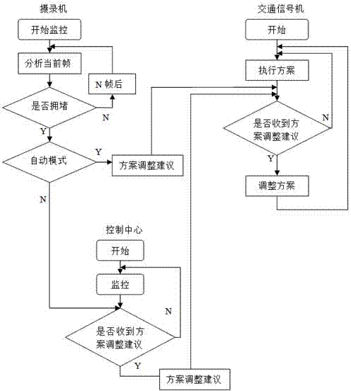
[0020] Such as figure 1 As shown, a traffic congestion relief method based on the linkage of traffic signals and video surveillance includes the following steps:

[0021] S1. The traffic signal sends the phase information of its current configuration scheme to the camcorder in real time, and the camcorder adds the received phase information to the corresponding frame of the video picture it shoots in real time in the form of digital watermark, and then Send the video to the control center in real time;

[0022] The control center adjusts the current configuration scheme of the traffic signal according to the traffic flow information and phase information in the video, such as extending the green light time in a certain direction, shortening the red light time in a certain direction, and so on.

[0023] S2. The camcorder monitors the intersect...


PUM


Abstract

The invention provides a traffic congestion dispersion method based on the traffic signal controller and video monitoring linkage. The method includes the steps that a video recorder conducts real-time monitoring on a crossing and analyzes traffic flow information of all directions of the crossing so that whether congestion happens or not can be judged; the video recorder automatically generates scheme adjustment suggestions according to the congestion information of a certain direction, and the video recorder is then in communication with the traffic signal controller so that the renewing mode of configuration schemes of the traffic signal controller can be obtained; in the automatic mode, the video recorder sends the congestion information of the direction and the scheme adjustment suggestions to the traffic signal controller, and the traffic signal controller adjusts the current configuration scheme according to the integration result of the congestion information of all the directions and the scheme adjustment suggestions. By means of the video monitoring and traffic signal controller linkage, the traffic light release time of the traffic signal controller can be adjusted according to the real-time traffic flow information, the traffic pressure is greatly relieved, the utilization rate of existing resources is increased, and meanwhile the manual cost of traffic congestion dispersion is reduced.

Description

technical field [0001] The invention relates to a traffic jam dredging method based on the linkage of traffic signal machines and video monitoring. Background technique [0002] With the increase of vehicles, the roads will be very congested every morning and evening after get off work and during holidays, especially some main roads, with heavy traffic volume, many intersections, and extremely complicated traffic conditions. The distance between each intersection is different, and There are also many differences in the traffic volume of each road intersecting with the main road. [0003] Although the current traffic signal can switch between multiple time periods a day, and each time period can use different schemes, the scheme for a certain period of time is fixed, which cannot adapt to the situation of large changes in traffic flow. When the other direction is smooth, automatic adjustment cannot be performed, which not only causes a great waste of public transportation r...

Claims


Application Information

Patent Timeline
Patent Type & Authority Applications(China)
IPC IPC(8): G08G1/08
CPCG08G1/08
Inventor 陈发钢梁子君李红涛
Owner ANHUI KELI INFORMATION IND
Why Eureka
Try Eureka