
Fuse resistor

A technology of resistors and fuses, applied in resistors, resistor parts, resistors that respond to current, etc., can solve problems such as product temperature rise, temperature fuse resistors are difficult to automate, etc., to prevent short circuits, easy automation, and simplification The effect of the manufacturing process

Active Publication Date: 2015-06-24
SMART ELECTRONICS CO LTD
View PDF7 Cites 6 Cited by
  • Summary
  • Abstract
  • Description
  • Claims
  • Application Information

AI Technical Summary

Problems solved by technology

[0009] However, in the example of the above-mentioned Korean patent-registered thermal cutoff, the resistor body is provided on only one side of the thermal cutoff, and therefore, if the heat generated by applying the rated current is not dissipated, in the normal state the Product temperature will rise
[0010] Furthermore, in the above-mentioned Korean registered patent, wires connecting the resistor body and the thermal fuse and wires extending to the outside of the case are necessary, and thus the manufacture of such thermal fuse resistors is difficult to automate

Method used


Image

  • Fuse resistor
  • Fuse resistor
  • Fuse resistor

Examples


Embodiment Construction

[0065] Preferred specific embodiments of the present invention will be described in detail below with reference to the accompanying drawings.

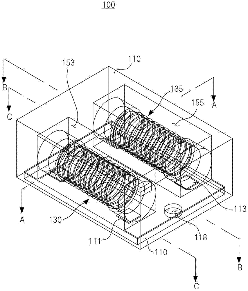
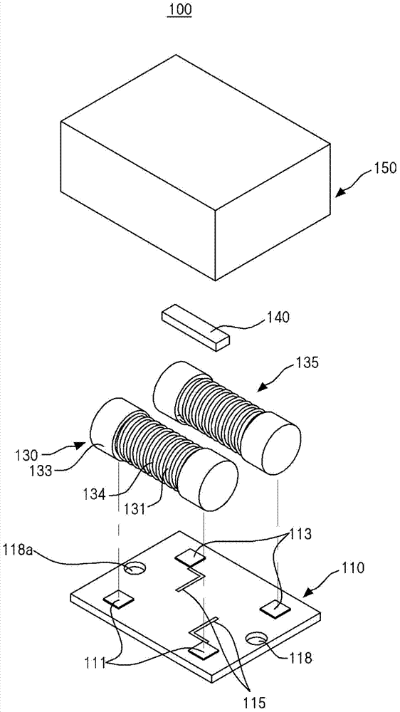
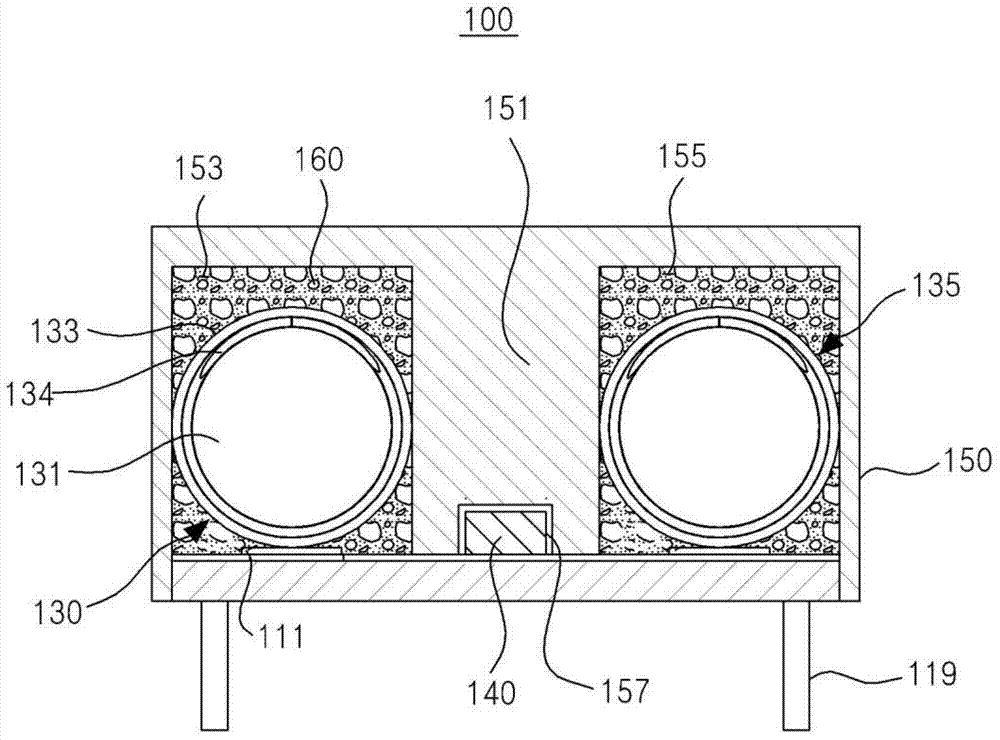
[0066] Please refer to Figures 1 to 5 , the fuse resistor 100 according to the present invention is designed to be used in electronic circuits of electronic products, and the fuse resistor 100 generally includes a substrate 110, a first resistive element 130, a second resistive element 135, a temperature fuse 140 and The casing 150 , wherein the casing 150 accommodates the first resistance element 130 , the second resistance element 135 and the thermal fuse 140 .

[0067] A first resistive electrode 111, a second resistive electrode 113, and a plurality of fuse electrodes 115 are provided on the substrate 110, so that the first resistive element 130, the second resistive element 135, and the thermal fuse 140 can be respectively disposed on On the first resistor electrode 111 , the second resistor electrode 113 and the fuse electrodes...


PUM


Abstract

The present invention relates to a fuse resistor and, more specifically, to a fuse resistor which can reduce melting time since a first and second resistance elements are heated on both sides of a thermal fuse when an over voltage or an over current is applied, can obtain a minimum space which can be reliably fused and can prevent short by inserting a thermal fuse into a thermal fuse receiving groove formed on an insulation film formed on a case, and has a structure easy to be automated because of mounting the resistance elements and thermal fuse on a substrate in a surface mounted method, and to a method for manufacturing the same.

Description

technical field [0001] The present invention relates to a fuse resistor, and more particularly to a fuse resistor. When an overvoltage or overcurrent is applied, the first resistance element and the second resistance element disposed on both sides of the thermal fuse generate heat, and thus shorten the cut-off time. When the thermal fuse is turned on, the thermal fuse is inserted into the thermal fuse receiving groove, wherein the thermal fuse receiving groove is constituted by a partition wall formed in the housing, and thus ensures a minimum space for stably disconnecting the thermal fuse, and prevents the occurrence of a short circuit , and the resistive elements and the temperature fuse are surface-mounted on a substrate, and thus make automation easier, thereby disclosing a manufacturing method of the fuse resistor. Background technique [0002] In general, in the electronic circuits of large electronic products such as LCD TVs or PDP TVs, or portable electronic devices...

Claims


Application Information

Patent Timeline
IPC IPC(8): H01C1/02H01C3/20
CPCH01C1/014H01C1/024H01C3/14H01C7/13H01H85/048
Inventor 姜斗园金炫昌李京美安相玟文皇帝申雅岚姜泰宪
Owner SMART ELECTRONICS CO LTD
Learn More