Intelligent charging spiral track take-up and pay-off device
A spiral track and intelligent charging technology, applied in the direction of the bendable lead wire device, etc., can solve the problems of inconvenient dragging, high cost, and easy to be stepped on by people coming and going, so as to save manpower, improve service life, drag and drop convenient effect
- Summary
- Abstract
- Description
- Claims
- Application Information
AI Technical Summary
Problems solved by technology
Method used
Image
Examples
Embodiment 1
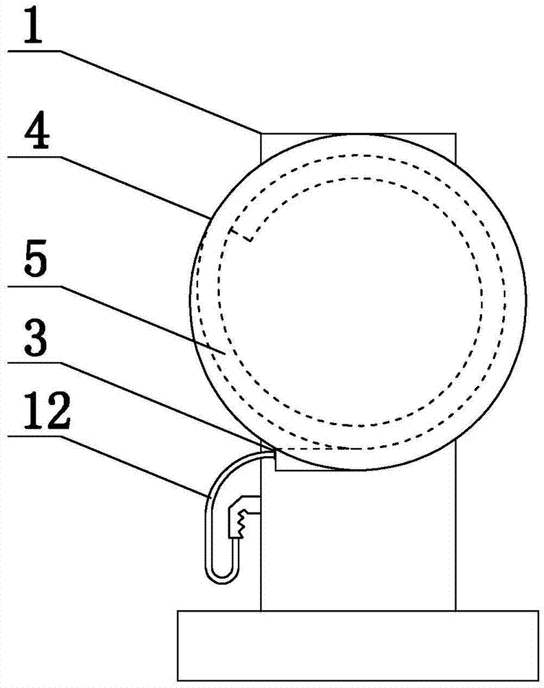
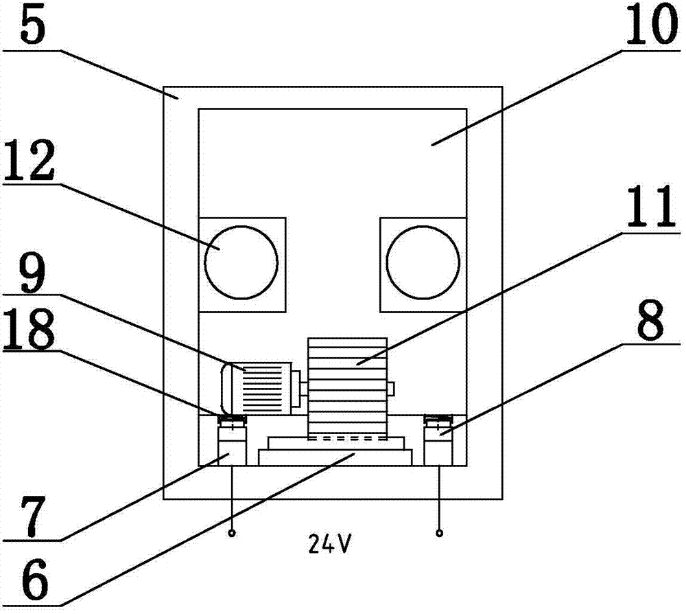
[0022] Embodiment 1: as figure 1As shown, the intelligent charging spiral track take-up and take-up device of the present invention includes a charging pile 1, an automatic take-up device 2 is provided on the charging pile 1, an automatic take-up device 2 is provided with an outlet 3, and an automatic take-up device 2 It includes a disc-shaped shell 4, a spiral track 5 is arranged inside the shell 4, a slide rail 6 adapted to the track is arranged in the middle of the track, a slide block 10 is arranged on the slide rail 6, and conductors are arranged on both sides of the slide rail 6. 7. There is a conductor B8 on the slider 10, and the conductor B8 is installed on the slider 10 through a spring 18. The conductor B8 and the conductor 7 are in contact with each other. The slider 10 is equipped with a motor 9, and the rotor of the motor 9 is provided with a gear 11. The gear 11 cooperates with the slide rail 6, the power end of the motor 9 is connected to the conductor B8, one ...
Embodiment 2
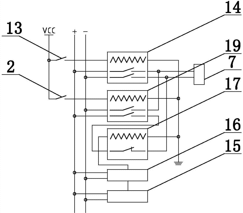
[0023] Embodiment 2: on the basis of the structure described in embodiment 1, as figure 2 As shown, switch 13, switch A2, relay 14 and relay A19 are arranged on the automatic wire take-up device, and one end of the coil of relay 14 and relay A19 is connected to the DC power supply through switch 13 and switch A2 respectively, and the other end is grounded, and conductor 8 passes through The normally open contact of relay 14 is connected to the power supply in positive sequence, the conductor 8 is connected to the power supply in reverse sequence through the normally open contact of relay A19, the meter counter 15 is provided on the outlet 3, and the controller is provided on the automatic wire take-up device 2 16 and relay B17, the normally closed contact of relay B17 is connected between the normally open contact of power supply and relay 16, the signal output end of meter counter 15 is connected to controller 16, and the signal output end of controller 16 is connected to rel...
Embodiment 3
[0024] Embodiment 3: On the basis of the structure described in Embodiment 2, the slider 10 is provided with a pulley, the pulley is provided with a pulley cover, and the charging gun connection 12 bypasses the pulley and the pulley on the slider 10 in the spiral track 5 Gaps between pulley housings.
[0025] Operation steps and working principle:
[0026] In the smart charging spiral rail take-up and take-up device, the charging gun connection wire 12 is coiled in the automatic wire take-up device 2, and the charging gun connection wire 12 is put away by the automatic wire take-up device 2 when not charging, and only needs to be charged when charging. Pull out the charging gun connecting line 12 to the required length, because when the charging gun connecting line 12 is pulled out, the electric vehicle is already in place, ensuring that the electric vehicle will not be pressed against the charging gun connecting line 12, so that the charging gun connecting line 12 will not be...
PUM
 Abstract
Description
Claims
Application Information
 - R&D
- Intellectual Property
- Life Sciences
- Materials
- Tech Scout
- Unparalleled Data Quality
- Higher Quality Content
- 60% Fewer Hallucinations
Browse by: Latest US Patents, China's latest patents, Technical Efficacy Thesaurus, Application Domain, Technology Topic, Popular Technical Reports.
© 2025 PatSnap. All rights reserved.Legal|Privacy policy|Modern Slavery Act Transparency Statement|Sitemap|About US| Contact US: help@patsnap.com


