Quantum interference device, atomic oscillator, electronic device, and moving object
A quantum interference and frame technology, applied in the field of moving objects, can solve problems such as the inability to detect EIT signals with high precision and the decrease in the accuracy of the oscillation frequency of atomic oscillators
- Summary
- Abstract
- Description
- Claims
- Application Information
AI Technical Summary
Problems solved by technology
Method used
Image

Examples
no. 1 Embodiment approach >
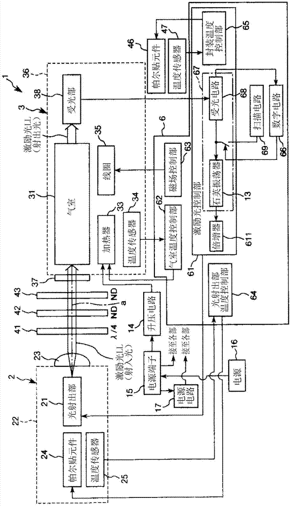
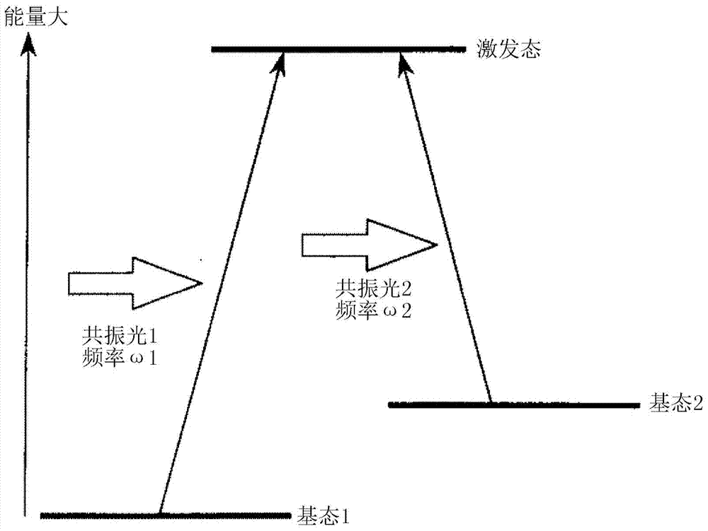
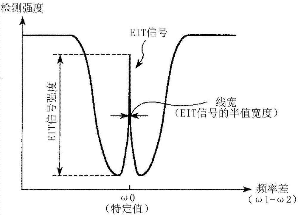
[0048] figure 1 It is a schematic diagram showing the schematic configuration of the atomic oscillator according to the first embodiment of the present invention. also, figure 2 is a diagram illustrating the energy states of alkali metals, image 3 It is a graph showing the relationship between the frequency difference between the two lights emitted from the light emitting part and the intensity of the light detected by the light receiving part and the light receiving circuit.
[0049] figure 1 The illustrated atomic oscillator 1 is an atomic oscillator utilizing the quantum interference effect.
[0050] Such as figure 1 , Figure 4 As shown, this atomic oscillator 1 has a first unit 2 as a unit on the light emitting side, a second unit 3 as a unit on the light detecting side, optical components 41, 42, 43 arranged between the units 2, 3, Peltier element 46, temperature sensor 47, control unit 6 for controlling first unit 2, second unit 3 and Peltier element 46, first s...
no. 2 Embodiment approach >
[0216] Next, a second embodiment of the present invention will be described.
[0217] Figure 8 It is a schematic diagram for explaining the second substrate of the atomic oscillator according to the second embodiment of the present invention. In addition, in the following description, regarding the second embodiment, the differences from the first embodiment will be mainly described, and the description of the same matters will be omitted.
[0218] Such as Figure 8 As shown, in the second embodiment, in the second substrate 82, the ground area 821 of the gas chamber temperature control unit 62 and the light emission unit temperature control unit 64 which are analog circuits is separated from the ground area 822 of the digital circuit 66. . In addition, the ground area 821 is arranged on one end side of the second substrate 82, that is, on the Figure 8 On the left side of the figure, the ground area 822 is disposed on the other end side of the second substrate 82, that i...
PUM
 Abstract
Description
Claims
Application Information
 - R&D
- Intellectual Property
- Life Sciences
- Materials
- Tech Scout
- Unparalleled Data Quality
- Higher Quality Content
- 60% Fewer Hallucinations
Browse by: Latest US Patents, China's latest patents, Technical Efficacy Thesaurus, Application Domain, Technology Topic, Popular Technical Reports.
© 2025 PatSnap. All rights reserved.Legal|Privacy policy|Modern Slavery Act Transparency Statement|Sitemap|About US| Contact US: help@patsnap.com