Switching circuit and lamp compatible with fluorescent lamp ballast

A conversion circuit and ballast technology, applied in the direction of electric lamp circuit layout, light source, electric light source, etc., can solve the problems of not being able to connect directly to electricity, troublesome installation and replacement, troublesome use and replacement, etc., to achieve cost reduction, convenient replacement, The effect of high work efficiency

Inactive Publication Date: 2015-06-24
JINGSAM ILLUMINATION
View PDF7 Cites 56 Cited by
  • Summary
  • Abstract
  • Description
  • Claims
  • Application Information

AI Technical Summary

Problems solved by technology

[0002] With the popularization of contemporary LED lighting, LED lights have entered the era of household use. However, fluorescent lamps for household use are generally fluorescent lamps. Ballasts, and LED fluorescent lamps are generally not compatible with the ballasts of such lamps, which brings troubles to installation and replacement. During installation, it is necessary to disassemble and change the wiring. Once the LED lamp is broken, it cannot be used. Fluorescent lamps are connected to emergency, which brings troubles to use and replacement.
[0003]In the prior art, there are already some LED lamp devices compatible with fluorescent lamp ballasts, but they can only be compatible with one-to-multiple ballasts and cannot be directly connected Electricity, but can not be compatible with 1 tow multi-type ballasts when it can be directly connected to electricity, which requires a device that can be fully compatible with direct connection and 1 tow multi-type ballasts

Method used


Image

  • Switching circuit and lamp compatible with fluorescent lamp ballast
  • Switching circuit and lamp compatible with fluorescent lamp ballast
  • Switching circuit and lamp compatible with fluorescent lamp ballast

Examples


specific Embodiment 1

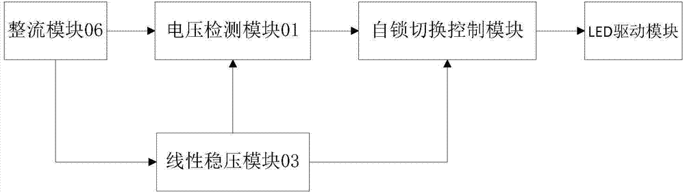
[0026] Such as picture The block diagram of a conversion circuit compatible with fluorescent lamp ballasts shown in 1 picture , including a rectifier module 06, a switching module, and an LED driver module 05; the output terminal of the rectifier module 06 is connected to the input terminal of the switching module; the output terminal of the switching module is connected to the input terminal of the LED driver module 05 ; the rectification module 06, which is used to convert the alternating current of the external power supply into direct current and output it; the switching module performs impedance switching when the voltage value output by the rectification module 06 is lower than a preset threshold value, and increases the conversion The equivalent impedance of the circuit.

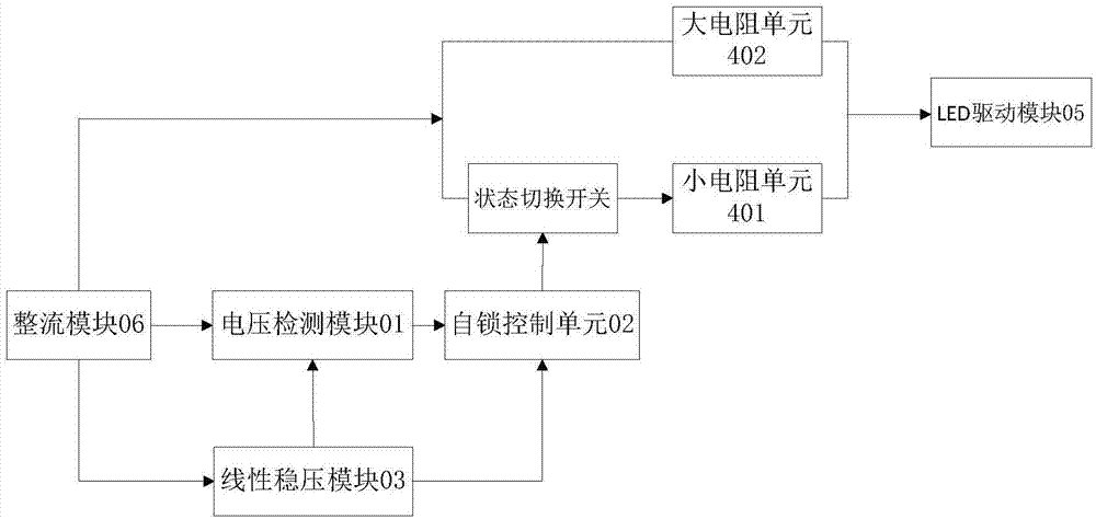
[0027] Such as picture The switching module shown in 2 shows picture , the switch module includes a linear voltage regulator module 03, a voltage detection module 01, a self-locking switch control ...

specific Embodiment 2

[0038] An LED lamp compatible with a fluorescent lamp ballast includes an LED module and a conversion circuit compatible with the fluorescent lamp ballast, and the output end of the LED driving module 05 is connected to the LED module.

[0039] The output end of the HV9910 chip is connected to the LED light.

[0040] In this embodiment, the switch working state and the linear working state of the HV9910 chip are mainly used. The working state of the switch means that when the voltage of the internal power supply terminal VDD of the HV9910 chip is greater than the undervoltage lockout voltage threshold UVLO of VDD, the drive output terminal DRV outputs a high level, and at this time the output current is limited by the external third field effect transistor M3. works with peak current.

[0041] The linear working state means that when the voltage of the linear dimming terminal LD ​​of the HV9910 chip is lower than 250mV, the HV9910 chip continuously adjusts the output current ...


PUM


Abstract

The invention discloses a switching circuit which is compatible with fluorescent lamp ballast. The switching circuit comprises a rectifying module, a switching module and an LED driving module. The output end of the rectifying module is connected with the input end of the switching module. The output end of the switching module is connected with the input end of the LED driving module. The rectifying module is used for converting an alternating current of an external power supply into a direct current, and then outputting the direct current. When a voltage value output by the rectifying module is lower than a preset threshold value, impedance switching is carried out on the switching module, and equivalent impedance of the switching circuit is increased. The invention further discloses an LED lamp which is compatible with the fluorescent lamp ballast. The LED lamp comprises an LED module and the switching circuit which is compatible with the fluorescent lamp ballast. The output end of the LED driving module is connected with the LED module. The LED lamp which adopts the switching circuit can be fully compatible with direct power connection and one-with-one-type and one-with-more-type ballast of a current fluorescent lamp, and has the advantages of being simple and efficient in design, convenient to replace, and low in cost.

Description

technical field [0001] The invention relates to the technical field of lighting devices, in particular to a conversion circuit compatible with a fluorescent lamp ballast and a lamp. Background technique [0002] With the popularization of modern LED lighting, LED lamps have entered the household era. However, household fluorescent lamps are generally fluorescent lamps. These lamps are generally equipped with inductive or electronic ballasts, and LED fluorescent lamps are generally not compatible with this type of lamps. ballast, which brings troubles to installation and replacement. It needs to be disassembled and changed wiring during installation. Once the LED lamp is broken, it cannot be connected with a traditional fluorescent lamp for emergency, which brings troubles to use and replacement. [0003] In the prior art, there are already some LED lamp devices compatible with fluorescent lamp ballasts, but they can only be compatible with 1-to-multi-type ballasts and canno...

Claims


Application Information

Patent Timeline
Patent Type & Authority Applications(China)
IPC IPC(8): H05B37/02
Inventor 郑淑子
Owner JINGSAM ILLUMINATION
Why Eureka
Try Eureka