Molded fiber-reinforced composite material and manufacturing method therefor

A composite material, fiber-reinforced technology, applied in shielding materials, chemical instruments and methods, synthetic resin layered products, etc., can solve problems such as thickening of thickness

Inactive Publication Date: 2015-06-24
MITSUBISHI CHEM CORP
View PDF7 Cites 5 Cited by
  • Summary
  • Abstract
  • Description
  • Claims
  • Application Information

AI Technical Summary

Problems solved by technology

In this case, the function as a structural body with strength and the function as an exterior are separated, and members of each function are combined, which causes the thickness of the display side to become thicker.

Method used


Image

  • Molded fiber-reinforced composite material and manufacturing method therefor
  • Molded fiber-reinforced composite material and manufacturing method therefor
  • Molded fiber-reinforced composite material and manufacturing method therefor

Examples


Embodiment 1

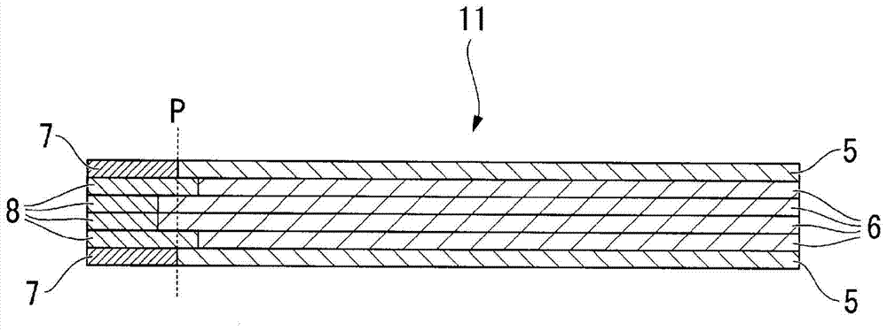
[0080] in order to achieve image 3 The fiber-reinforced composite material molded body shown is a 0° direction formed by joining carbon fiber prepreg (unidirectional material) in the 0° direction and glass fiber prepreg (unidirectional material) in the 0° direction in the extending direction The prepreg joint sheet of the 90° direction is formed by joining the carbon fiber prepreg (unidirectional material) in the 90° direction and the glass fiber prepreg (unidirectional material) in the 90° direction in the extending direction. A bonded sheet was used, and a laminate in which six layers of the bonded sheet were laminated in the order [90° / 0° / 0° / 0° / 0° / 90°] was produced. At this time, the junction (junction line) between the carbon fiber prepreg and the glass fiber prepreg is as follows: image 3 In this way, each of them is shifted by 10mm from the joining center P. In addition, a glass fiber prepreg is arranged at one end. Next, the prepreg was pressed at a pressure of 3 M...

Embodiment 2

[0082] The position of the bonding line between carbon fiber prepreg and glass fiber prepreg is as follows: Figure 4 Except for such changes, it was carried out in the same manner as in Example 1 to obtain a thin plate-shaped fiber-reinforced composite material molded body 21 with a thickness of 0.60 mm.

Embodiment 3

[0084] From the structure of Example 1, the glass fiber prepreg of the outermost layer is changed from a unidirectional material to a fabric material, and the joining positions other than the outermost layer are changed, thereby obtaining Figure 5 Such a fiber-reinforced composite material molded body 31 .


PUM

PropertyMeasurementUnit
thicknessaaaaaaaaaa
thicknessaaaaaaaaaa

Abstract

This sheet-shaped molded fiber-reinforced composite material is provided with the following: an EM-blocking prepreg comprising conductive fibers and a thermosetting matrix resin; an EM-transparent prepreg comprising non-conductive fibers and a thermosetting matrix resin; a first layer formed by joining the EM-blocking prepreg and the EM-transparent prepreg together, at a join line, in a direction perpendicular to the thickness direction of the molded fiber-reinforced composite material; a second layer that is formed on top of the first layer and contains the EM-transparent prepreg, disposed so as to cover at least part of the aforementioned join line; and an EM-transparent section, in the aforementioned thickness direction, that does not contain the EM-blocking prepreg.

Description

technical field [0001] The present invention relates to a fiber-reinforced composite material molded body excellent in lightness, thinness, and rigidity. More specifically, it relates to a fiber-reinforced composite material molded article in which a part of thin plates made of reinforcing fibers and a thermosetting resin arranged continuously in a direction perpendicular to the thickness direction have high electromagnetic wave permeability in the thickness direction, and its Manufacturing method. [0002] this application claims priority based on Japanese Patent Application No. 2012-233554 for which it applied to Japan on October 23, 2012, The content is used here. Background technique [0003] Fiber-reinforced composite materials (hereinafter referred to as "FRP") are widely used in industries ranging from sports and leisure uses to automobiles and aircraft because they are lightweight, high-strength, and high-rigidity. [0004] FRP is also used for casings of electrica...

Claims


Application Information

Patent Timeline
Patent Type & Authority Applications(China)
IPC IPC(8): B32B5/28B32B27/04C08J5/04C08J5/08H05K9/00
CPCB32B5/26H05K9/009B32B2605/00B32B2605/18B32B2457/00B32B2307/212B32B2307/202B32B2262/101B32B2262/106B32B2250/20B32B2260/023B32B2260/046B29C70/882Y10T428/24124Y10T428/24752B29L2031/3475H05K9/0088B29C65/00B29C65/70B29C65/7802B29K2063/00B29K2105/12B29K2307/04B29K2309/08B29K2995/0005B29K2995/0011B29K2995/0027B29L2009/00
Inventor 吉田圭吾齐藤义明木场久雄寺泽知德
Owner MITSUBISHI CHEM CORP
Why Eureka
Try Eureka