Biometric information measuring apparatus
A technology of biological information and measurement equipment, which is applied in the field of biological information measurement equipment, and can solve problems such as difficulty in moving fingers of the wearer, difficulty in ensuring tightness, etc.
- Summary
- Abstract
- Description
- Claims
- Application Information
AI Technical Summary
Problems solved by technology
Method used
Image

Examples
Embodiment approach 1
[0137] (Overview of Biometric Information Measuring Device)
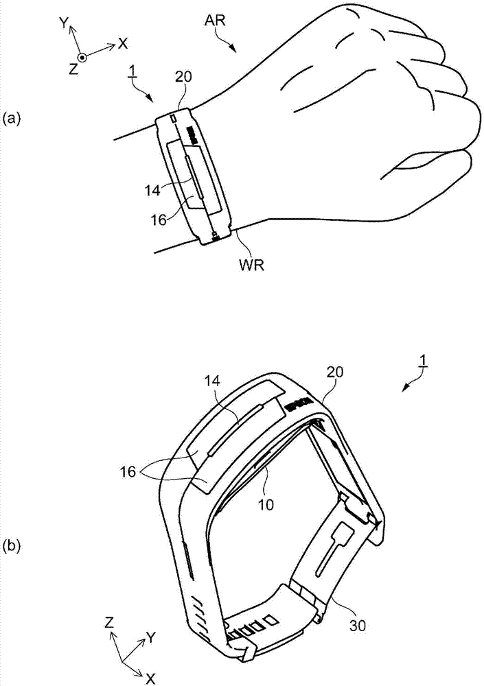
[0138] figure 1 (a) is a diagram showing the wearing state of the living body information measuring device according to Embodiment 1 worn on the living body. figure 1 (b) is a diagram showing an open state in which the living body information measuring device is detached from the living body.
[0139] The biological information measuring device (hereinafter, also referred to as measuring device) 1 according to the first embodiment is an electronic device that is worn on a living body (for example, a human body) whose biological information is to be measured, and measures biological information such as a pulse. . Such as figure 1 As shown in (a), the measurement device 1 is used by being worn on a measurement site (wrist, etc.) of a wearer (biological body) like a wristwatch. exist figure 1 (a) shows a state where the measurement device 1 is worn on the wrist WR of the wearer's left arm AR.
[0140] In this spe...
Deformed example 1
[0216] Figure 9 It is a perspective view of the periphery of the belt part according to Modification 1, corresponding to Figure 4 (b).
[0217] In the above-mentioned embodiment, it has been described that the plurality of adjustment hole portions 26 are formed in one row on the first belt portion 22 , but the present invention is not limited thereto, and a plurality of rows may be formed. For example, if Figure 9 As shown, along the extending direction of the first belt portion 22 , the rows composed of the plurality of adjustment hole portions 26 form two rows. In a preferable example, two claws 35 of the first sheet 31 are formed in two rows.
[0218] According to this configuration, since the engagement structure is formed in two rows, the first belt portion 22 and the first piece 31 can be firmly connected compared with the one-row engagement configuration. Moreover, since it becomes a point in design, it can also improve an aesthetics.
Deformed example 2
[0220] Figure 10 It is an expanded perspective view of the brief structure of the living body information measuring device related to Modification 2, corresponding to figure 2 .
[0221] In the above-mentioned embodiment, the case where the connecting portion 27 with the buckle portion 30 is formed in one place on the second belt portion 24 has been described, but it is not limited to this configuration, and may be formed in plural. For example, if Figure 10 As shown, the connecting portion 27 may be formed at two places along the extending direction of the second belt portion 24 . also, Figure 10 and figure 2 The only difference lies in the number of connecting parts 27.
[0222] With this configuration, when the second sheet 32 is connected to the second belt part 24, any one of the plurality of connection parts 27 can be selected and connected. Therefore, when adjusting the length of the annular opening in the initial setting, it is possible to adjust not only ...
PUM
 Abstract
Description
Claims
Application Information
 - R&D
- Intellectual Property
- Life Sciences
- Materials
- Tech Scout
- Unparalleled Data Quality
- Higher Quality Content
- 60% Fewer Hallucinations
Browse by: Latest US Patents, China's latest patents, Technical Efficacy Thesaurus, Application Domain, Technology Topic, Popular Technical Reports.
© 2025 PatSnap. All rights reserved.Legal|Privacy policy|Modern Slavery Act Transparency Statement|Sitemap|About US| Contact US: help@patsnap.com