Check patentability & draft patents in minutes with Patsnap Eureka AI!

Bioenergy brain pacemaker

A brain pacemaker and bioenergy technology, applied in the field of medical devices, can solve problems such as fear and anxiety, patient pain, increase the economic burden of patients and their families, and achieve the effect of small size and full collection

Inactive Publication Date: 2015-07-01
SECOND MILITARY MEDICAL UNIV OF THE PEOPLES LIBERATION ARMY
View PDF4 Cites 0 Cited by
  • Summary
  • Abstract
  • Description
  • Claims
  • Application Information

AI Technical Summary

Problems solved by technology

However, the battery life of the brain pacemaker is 5 to 8 years, and the battery of the brain pacemaker must be replaced by a surgical operation after the power is exhausted.
This will not only cause physical pain and psychological fear and anxiety to patients, but also increase the financial burden on patients and their families.

Method used


Image

  • Bioenergy brain pacemaker
  • Bioenergy brain pacemaker
  • Bioenergy brain pacemaker

Examples


Embodiment 1

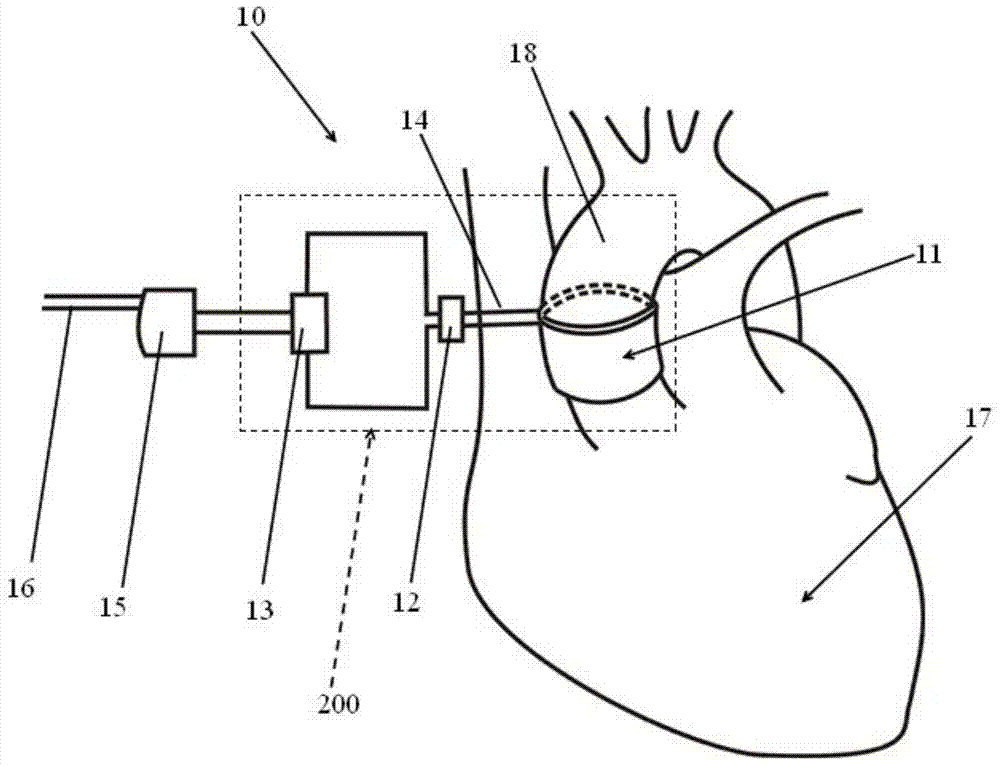
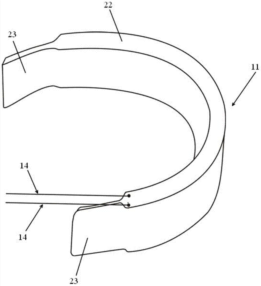
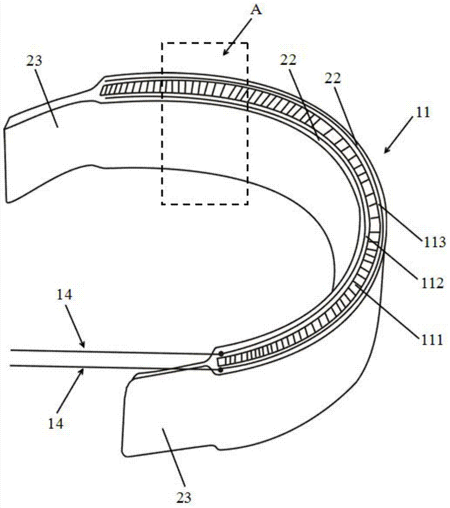
[0030] figure 1 It is a schematic diagram of a bioenergy brain pacemaker in Embodiment 1 of the present invention, such as figure 1 As shown, the bioenergy brain pacemaker 10 includes a power generation unit 200 , a pulse generator 15 , and a stimulating electrode 16 . The power generation unit 200 includes a power generation body 11 , an output electrode 14 , a rectification filter circuit 12 and an electric energy storage unit 13 . The power generating body 11 is an elastic annular structure, which can surround the aorta 18. The inside of the power generating body 11 is made of nano-scale piezoelectric material, so the deformation of the aorta can be used to generate electric energy. A rectification and filtering circuit 12 is connected behind the output electrode 14 of the power generation main body. The electric energy storage unit 13 is connected behind the rectification and filtering circuit 12 for storing electric energy for use by the pulse generator 15 . The pulse ...

Embodiment 2

[0042] In this embodiment, the shape of the power generating body 11 and the arrangement of the adjustment end 23 are the same as those in Embodiment 1, the difference is that in this embodiment, the piezoelectric material layer of the power generating body is made of nanoscale piezoelectric ceramic material.

[0043] Another difference is that in this embodiment, the adjustment end 23 is fixed by a titanium clip.

Embodiment 3

[0045] In this embodiment, the shape of the power generation body and the setting of the adjustment end are the same as in Embodiment 1, the difference is that in this embodiment, the piezoelectric material layer of the power generation body is made of piezoelectric polymer, and the adjustment end is made of adhesive Fix by gluing.


PUM


Abstract

The invention provides a bioenergy brain pacemaker, comprising a pulse generator and exciting electrodes. The bioenergy brain pacemaker is characterized by also comprising an electricity generation portion which comprises an electricity generation main body, two adjusting ends, an output electrode, a macromolecule packaging material and an electric energy accumulation unit. The electricity generation main body is used to surround the aorta, so as to acquire mechanical energy generated when the aorta expands, and converts the mechanical energy to electric energy. The electricity generation main body is in a multilayered film structure. The electricity generation main body comprises a piezoelectric layer in a central layer, and a first electrode layer and a second electrode layer respectively on two sides of the piezoelectric layer. The macromolecule packaging material covers surfaces of the electricity generation main body, the adjusting ends, and the output electrode. The two adjusting ends are disposed on two ends of the electricity generation main body and used to adjust the diameter of the electricity generation main body. The output electrode is used to transmit electric energy to the electric energy accumulation unit. The electric energy accumulation unit is used to store electric energy and supply power for the pulse generator and the exciting electrodes. The bioenergy brain pacemaker can be used for whole life without changing cells.

Description

technical field [0001] The invention relates to a brain pacemaker, which belongs to the field of medical equipment. Background technique [0002] With the deepening of human understanding of various diseases, more and more diseases can be diagnosed or treated with implanted electronic devices. [0003] Among them, the implanted brain pacemaker can stimulate the nerves that control movement in the brain, inhibit the abnormal signals that cause Parkinson's disease, relieve or even eliminate the symptoms of tremor, stiffness, and slow movement in patients, and restore their original mobility and self-care ability. However, the service life of the battery of the brain pacemaker is 5 to 8 years, and the battery of the brain pacemaker must be replaced by a surgical operation after the power is exhausted. This will not only cause physical pain and psychological fear and anxiety to patients, but also increase the financial burden on patients and their families. Contents of the i...

Claims


Application Information

Patent Timeline
Patent Type & Authority Applications(China)
IPC IPC(8): A61N1/378
Inventor 张浩曲丹徐志云
Owner SECOND MILITARY MEDICAL UNIV OF THE PEOPLES LIBERATION ARMY
Features
  • R&D
  • Intellectual Property
  • Life Sciences
  • Materials
  • Tech Scout
  • Unparalleled Data Quality
  • Higher Quality Content
  • 60% Fewer Hallucinations
Learn More