Hot extrusion die with improved structure

A hot extrusion die and structure improvement technology, applied in the direction of metal extrusion dies, etc., can solve problems such as difficult welding, product cracking and damage, and affecting product strength, so as to achieve the effect of high overall strength and not easy to crack and damage

Inactive Publication Date: 2015-07-01
捷安特轻合金科技(昆山)股份有限公司
View PDF8 Cites 3 Cited by
  • Summary
  • Abstract
  • Description
  • Claims
  • Application Information

AI Technical Summary

Problems solved by technology

[0002] All kinds of profiles are formed by hot extrusion dies. Generally, hot extrusion dies are composed of an upper die and a lower die. The upper die is equipped with a guide plate and a core head. The diversion hole between the bridges enters the mold after diversion, then flows into the welding chamber, and then converges after entering the welding chamber, and then enters the molding space formed by the core head and the forming hole for extrusion molding, and finally from the discharge Hole discharge, the current common bridge position is linear along the radial direction of the upper die, the material enters the welding chamber along the diversion hole, and the material enters the forming hole after converging in the welding chamber to form, but because the bridge position is linear , then the material flows directly into the welding chamber along the split holes, the materials in each split hole are difficult to weld well, and the surface of the formed product will produce a linear weld line along its length, which affects the strength of the product , the product is prone to cracking and damage during use

Method used


Image

  • Hot extrusion die with improved structure
  • Hot extrusion die with improved structure
  • Hot extrusion die with improved structure

Examples


Embodiment

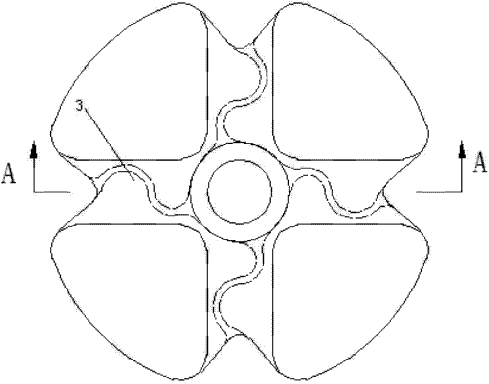
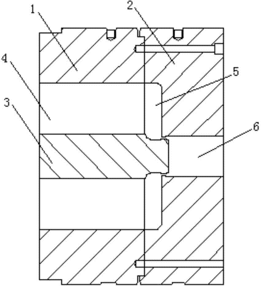
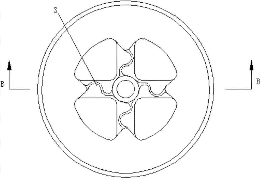
[0013] Embodiment: A hot extrusion die with improved structure, including an upper die 1 and a lower die 2 that can be superimposed and connected together. The feed end of the upper die 1 is provided with a guide plate, and a number of bridge positions are provided on the guide plate 3. Diverting holes 4 are formed between each bridge position 3, and the lower mold 2 is sequentially provided with a connected welding chamber 5 and a discharge hole 6 from the feed end to the discharge end. The welding chamber 5 and the upper mold 1 The split hole 4 is connected, the core head of the upper mold 1 is inserted into the forming hole of the lower mold 2, each bridge position 3 of the upper mold 1 extends in a curved state along the radial direction of the upper mold 1, and the material flows from the upper mold 1. The diversion hole 4 flows into the welding chamber 5 of the lower mold 2. Since the bridge position 3 of the upper mold 1 is curved, the diversion hole 4 also has a corresp...


PUM


Abstract

The invention discloses a hot extrusion die with an improved structure. The hot extrusion die comprises an upper die and a lower die which can be superposed and connected together back and forth, wherein a guide plate is arranged at the feeding end of the upper die; multiple bridge locations are formed on the guide plate; a shunt hole is formed between every two bridge locations; a welding chamber and a discharge hole which are communicated with each other are sequentially formed from the feeding end to the discharging end of the lower die; the welding chamber is communicated with the shunt holes in the upper die; a core head of the upper die is inserted into a molding hole of the lower die; and each bridge location of the upper die extends in a curve state along the radial direction of the upper die. The bridge locations of the upper die are designed into a curve structure, and materials entering the shunt holes enter the welding chamber via the shunt holes of the curve shape and form turbulence in the welding chamber, so that the materials flowing into the welding chamber in each shunt hole are fully welded, the welding line on the surface of the product molded by the materials by virtue of the molding hole extends in a spiral curve mode, the overall strength is high, and the die is difficult to crack and damage during bending, cold-drawing and stretching.

Description

technical field [0001] The invention relates to an extrusion die, in particular to a hot extrusion die with improved structure. Background technique [0002] All kinds of profiles are formed by hot extrusion dies. Generally, hot extrusion dies are composed of an upper die and a lower die. The upper die is equipped with a guide plate and a core head. The diversion hole between the bridges enters the mold after diversion, then flows into the welding chamber, and then converges after entering the welding chamber, and then enters the molding space formed by the core head and the forming hole for extrusion molding, and finally from the discharge Hole discharge, the current common bridge position is linear along the radial direction of the upper die, the material enters the welding chamber along the diversion hole, and the material enters the forming hole after converging in the welding chamber to form, but because the bridge position is linear , then the material flows directly ...

Claims


Application Information

Patent Timeline
Patent Type & Authority Applications(China)
IPC IPC(8): B21C25/02
CPCB21C25/02
Inventor 涂季冰李展志吕传锋高爱林
Owner 捷安特轻合金科技(昆山)股份有限公司
Why Eureka
Try Eureka