

Motor vehicle stress application controller and brake linkage device
A technology of linkage device and controller, which is applied in the layout of power plant control mechanism, foot-operated starting device, vehicle components, etc., and can solve problems such as vehicle acceleration, accidents, and difficulty in adapting to the driver
- Summary
- Abstract
- Description
- Claims
- Application Information
AI Technical Summary
Problems solved by technology
Method used
Image

Examples
Embodiment Construction
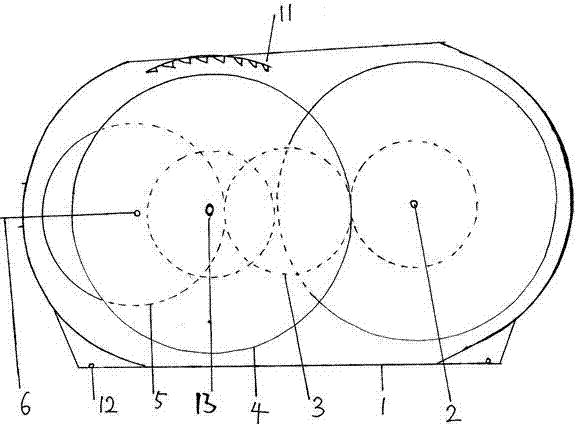
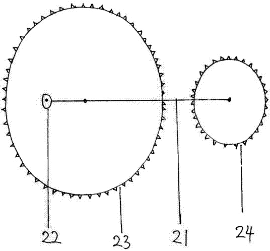
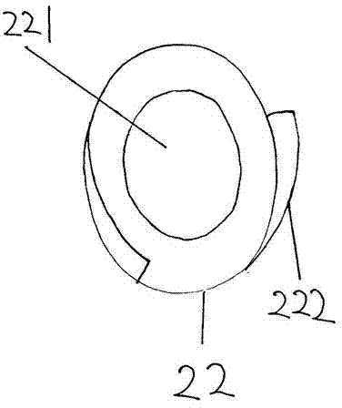
[0029]The embodiment of the motor vehicle booster controller and the brake linkage device of the present invention, as shown in the figure, the booster controller includes a main housing 1, which is divided into two gear compartments on the left and right, and a booster is installed on the wall of the gear compartment on one side. The shaft hole 13 of the brake wheel 4 of the booster, the shaft hole 13 of the brake wheel 4 of the booster is O-shaped, which is slightly larger than the shaft of the brake wheel 4 of the booster, the main housing 1 and the brake wheel 4 of the booster The corresponding inner upper part is distributed with ratchets 11, the front part of the main housing 1 has a shaft hole for installing the force-bearing wheel 5 of the booster, and the outer shell on the rear side of the main housing 1 and the gear compartment in the middle are installed with a booster. The shaft hole of the drive wheel 3, the rear part of the main housing is equipped with a power g...
PUM
 Abstract
Description
Claims
Application Information