Mid-partition rectangular tunnel segmental lining and segment splicing method

A technology of tunnel segment and segment, which is applied in the direction of tunnel lining, tunnel, wellbore lining, etc., to achieve the effect of reducing bending moment, improving economy, and reducing the cost of manufacturing molds

Active Publication Date: 2015-07-01
CHINA RAILWAY ENGINEERING EQUIPMENT GROUP CO LTD
View PDF8 Cites 9 Cited by
  • Summary
  • Abstract
  • Description
  • Claims
  • Application Information

AI Technical Summary

Benefits of technology

This technology allows for better use of space by utilizing circular tunnels with partitions made up from two different materials instead of one material altogether. These partitions help distribute stress more evenly throughout them, which increases their lifespan compared to traditional methods like reinforced concrete or steel frame systems. Additionally, these partitions can be easily installed without requiring excessive labor costs during installation. Overall, this new method enhances the durability and economic performance of tunnel constructions while maintaining good quality standards.

Problems solved by technology

This patented technical problem addressed in this patents relates to improving the efficiency with which trenches used during civil works or transportations have been dug up without causing damage from environmental factors such as water intrusion.

Method used


Image

  • Mid-partition rectangular tunnel segmental lining and segment splicing method
  • Mid-partition rectangular tunnel segmental lining and segment splicing method
  • Mid-partition rectangular tunnel segmental lining and segment splicing method

Examples


Embodiment 1

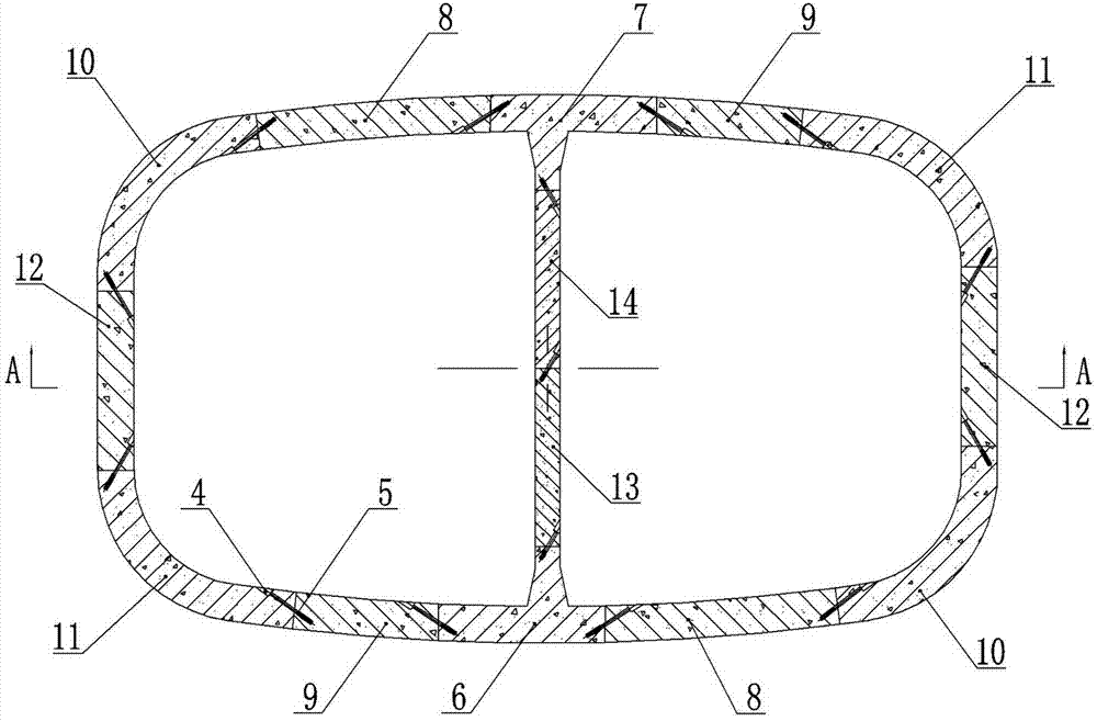
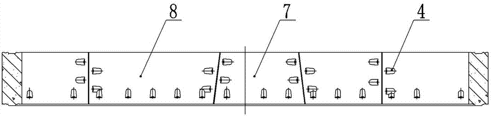
[0032] Embodiment one: see Figure 1-Figure 4 , a rectangular tunnel segment lining for a partition wall, the tunnel section form is a rectangular straight wall arch, the segment lining includes an L-shaped segment ring 1 and an R-shaped segment ring 2, and the L-shaped tube The segment rings 1 and R-shaped segment rings 2 are alternately arranged in a cycle along the direction of the tunnel, and the mid-span areas of the upper and lower arches of the L-shaped segment rings 1 and R-shaped segment rings 2 are provided with intermediate partition walls 3. Both the L-shaped segment ring 1 and the R-shaped segment ring 2 include a plurality of annular segment segments and intermediate wall segments assembled in a ring shape, and the annular segment segments and the intermediate segment segments The segments of the partition wall are made of reinforced concrete. The splicing longitudinal joints of two adjacent segments on the L-shaped segment ring 1 and the splicing longitudinal jo...

Embodiment 2

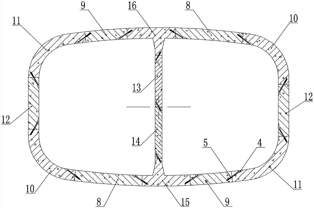
[0034] Embodiment two: see Figure 1-Figure 3 , the structure of this embodiment is basically the same as that of Embodiment 1, and the similarities will not be repeated. The splicing ring seams of segment rings are mortise and tenon joints, wedge joints or tongue and groove joints.

Embodiment 3

[0035] Embodiment three: see Figure 1-Figure 4 , the structure of this embodiment is basically the same as that of Embodiment 1 or 2, and the similarities will not be repeated. The difference is that the L-shaped segment ring 1 and the R-shaped segment ring 2 are all about the central axis of the tunnel It has a 180° symmetrical structure, and the L-shaped segment ring 1 includes capping blocks Q7 and T-blocks P6 respectively located in the middle of the upper arch and lower arch of the lining, and assembled in a rectangular ring between the capping block Q7 and the T-block P6 2 pieces of curved arch blocks B8, 2 pieces of curved arch blocks F9, 2 pieces of transition blocks C10, 2 pieces of transition blocks E11 and 2 pieces of straight wall blocks D12, the R-shaped segment ring 2 includes And the capping block S16 and T-shaped block R15 in the middle of the lower arch, and 2 pieces of arch blocks B8, 2 pieces of curved arch blocks F9, and 2 pieces of transition blocks assem...


PUM


Abstract

The invention relates to a device and method for solving the problems in the long-distance tunneling technology of a rectangular shielding machine, in particular to a mid-partition rectangular tunnel segmental lining and a segment splicing method. The runnel section of the segment lining is in a rectangular-ring vertical wall arch type or a curved wall arch type. Mid-partitions are arranged in midspan areas. The segment lining comprises L-shaped segment rings and R-shaped segment rings, the L-shaped segment rings and the R-shaped segment rings are alternately arranged in a circulated mode in the tunnel direction, and segment spliced longitudinal joints of the L-shaped segment rings and the R-shaped segment rings are in a joint staggered splicing type. Meanwhile, the segment splicing method of the matched mid-partition rectangular tunnel segmental lining is achieved through a shielding segment erector and a shape retainer.

Description


Claims


Application Information

Patent Timeline
Owner CHINA RAILWAY ENGINEERING EQUIPMENT GROUP CO LTD
Why Eureka
Try Eureka