
Automatic efficient energy-saving water wheel

A high-efficiency, energy-saving, waterwheel technology, used in engine components, machines/engines, impact engines, etc.

Inactive Publication Date: 2015-07-01
LIUZHOU JINGYANG ENERGY SAVING TECH RES DEV
View PDF4 Cites 1 Cited by
  • Summary
  • Abstract
  • Description
  • Claims
  • Application Information

AI Technical Summary

Problems solved by technology

[0003] The purpose of the present invention is to solve practical problems such as the shortage of existing energy sources and the lack of energy development technology, etc., to provide a device with advanced design performance, simple operation and wide application, automatic bucket water power generation, high efficiency, energy saving and environmental protection, safe and durable, convenient and durable, low cost and high return , an automatic high-efficiency energy-saving water wheel with high comprehensive cost performance and extremely obvious long-term benefits

Method used


Image

  • Automatic efficient energy-saving water wheel

Examples


Embodiment Construction

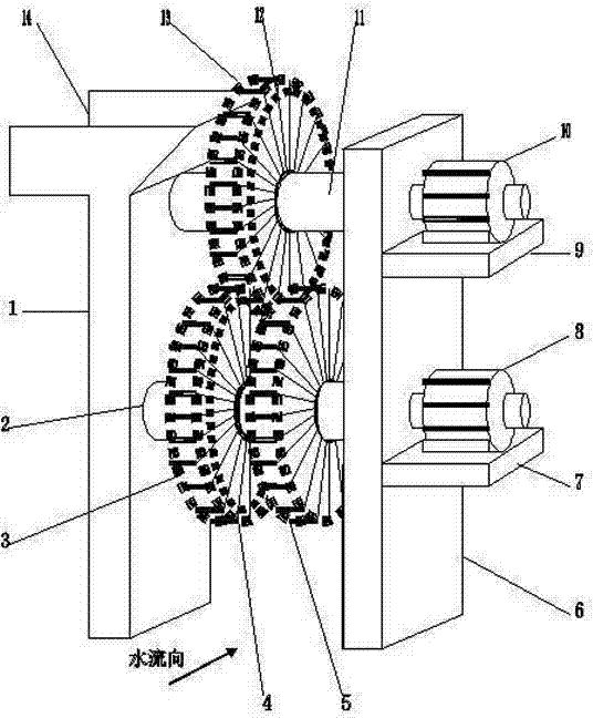
[0017] As shown in the accompanying drawings, the automatic high-efficiency and energy-saving water wheel of the present invention includes two parts: a main body and an attached body.

[0018] The main body includes a left water wheel 3, a lower drive circle 4, a right water wheel 5, a lower generator 8, an upper generator 10, an upper drive circle 12, and an upper water wheel 13, and the left water wheel 3 is arranged far away from the right water wheel. On the outer side of the lower rotating shaft on the left side of the car 5, its function is to receive hydraulic propulsion synchronously with the right water wheel 5 and drive the upper water wheel 13 and drive the lower generator 8 to generate electricity. Side and right water wheel 5 left sides and lower drive ring 4 side drive teeth are respectively interlocked with upper drive ring 12 side drive teeth on the left and right sides of upper water wheel 12, and its effect is to go up with upper water wheel 13 left and right...


PUM


Abstract

The invention discloses an automatic efficient energy-saving water wheel, and relates to net valves. The automatic efficient energy-saving water wheel is organically composed of a main body and accessory bodies including a left water wheel body, a right water wheel body, upper drive rings, lower drive rings, an upper electric generator, a lower electric generator, an upper water wheel body, a left support, a right support, an upper rotating shaft, a lower rotating shaft, an upper support, a lower support, a surge tank and the like. The left water wheel body and the right water wheel body are arranged on the outer sides of the two ends of the lower rotating shaft; and the upper drive rings are arranged on the left side and the right side of the upper water wheel body, and the lower drive rings are arranged on two sides of the left water wheel body and the right water wheel body. The upper electric generator and the lower electric generator are arranged on the upper side of the upper support and the upper side of the lower support. The upper water wheel body is arranged on the outer side of the upper rotating shaft; and the left support is arranged on the left side of the water wheel and the right support is arranged on the right side of the water wheel. The upper rotating shaft is arranged in a bearing of the upper water body, and the lower rotating shaft is arranged in a bearing of the left and right water wheel bodies; the upper support and the lower support are connected with the right support; and the surge tank is arranged at the upper end of the left support. The automatic efficient energy-saving water wheel is advanced in design performance, simple and easy to implement, wide in application, capable of realizing the hydroelectric generation of automatic buckets, efficient, environmentally friendly, safe, portable, durable, low in cost, high in return, and obvious in comprehensive benefits, and energy is saved.

Description

technical field [0001] The invention relates to a water wheel, in particular to an automatic high-efficiency and energy-saving water wheel. Background technique [0002] Now people have fully realized that the development of various social undertakings should be carried out simultaneously with energy conservation and environmental protection, and vigorously advocate comprehensive energy conservation, consumption reduction and efficiency enhancement, and the scientific utilization and development of water resources, which is hailed as the source of life, is particularly important. And along with the continuous development of industrial and agricultural production and people's life in urban and rural areas, resources, energy and hydropower are increasingly in short supply, while surface water flow and water energy of rivers and ditches widely distributed in urban and rural areas are mostly wasted. The technical installations of water and power generation are used for long-term...

Claims


Application Information

Patent Timeline
IPC IPC(8): F03B13/00
CPCF03B13/00F03B1/00F05B2220/706
Inventor 韦战
Owner LIUZHOU JINGYANG ENERGY SAVING TECH RES DEV
Learn More