
Clutch device for mini tiller

A clutch device and clutch technology, applied in the field of tillage machines, can solve problems such as the increased gap between the connecting sleeve and the connecting boss, the clutch cover needs to be strengthened, and the connecting boss is easy to be cut, so as to improve the service life and long service life , the effect that is not easy to fail

Inactive Publication Date: 2015-07-01
CHONGQING JIAXING IND
View PDF0 Cites 2 Cited by
  • Summary
  • Abstract
  • Description
  • Claims
  • Application Information

AI Technical Summary

Problems solved by technology

[0002] A clutch should be installed between the power unit and the transmission of the agricultural tiller. Most of the existing clutches are wet friction plate clutches. The clutch cover is made of aluminum alloy. The end plate of the clutch cover is provided with a boss connected to the center sleeve. The boss is inserted into the waist-shaped hole on the flange of the center sleeve, and rubber rings are respectively installed between the two sides of the boss and the waist-shaped hole. Swelling and deformation, and the power of the micro-tiller power device is relatively large. This existing buffer structure is prone to aging and failure after working for a period of time, resulting in the increase of the gap between the connecting sleeve and the connecting boss, and the increase of shear force, which not only causes The impact is increased during power transmission, which is easy to damage the transmission mechanism, and the connecting boss is also easy to be cut off
In addition, the engagement between the existing clutch cover and the friction active plate is easy to wear, and the clutch cover needs to be strengthened

Method used


Image

  • Clutch device for mini tiller
  • Clutch device for mini tiller

Examples


Embodiment Construction

[0014] Preferred embodiments of the present invention will be described below with reference to the accompanying drawings.

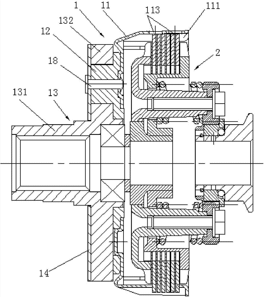
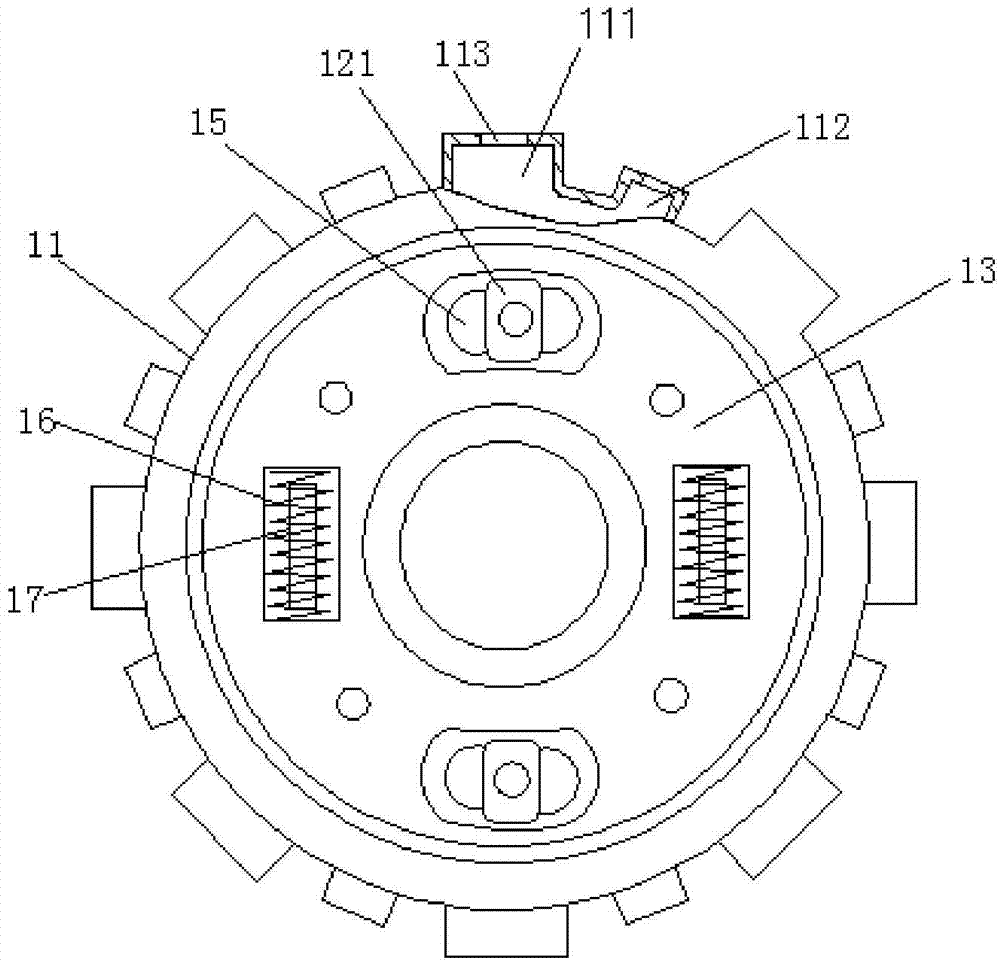
[0015] see figure 1 and figure 2 , a clutch device for a tiller, comprising a clutch cover assembly 1 and a center plate assembly 2 having a driving plate and a driven plate, the clutch cover assembly 1 includes a clutch cover 11 riveted together by rivets 18, a connecting convex plate 12 , Connection sleeve 13 and end plate 14. Clutch cover 11 is made by stamping steel plate. The cover ring of clutch cover 11 is an annular cover with continuous peripheral surface. On the inner side wall of the annular cover, there is an outwardly protruding engagement groove 111. The clutch cover 11 formed by stamping steel plate has a relatively high hardness. The common aluminum alloy cover is greatly improved, and the engaging groove 111 of the clamping active plate is not easy to be worn and stuck, which improves the service life of the clutch. On the annular co...


PUM


Abstract

The invention provides a clutch device for a mini tiller. The clutch device comprises a clutch housing component and a centre disc component with a driving piece and a driven piece, and characterized in that the clutch housing component comprises a clutch housing, a connecting sleeve and an end plate, which are riveted together; a buffering component is arranged between the clutch housing and the connecting sleeve; the buffering component comprises a spring unit and a rubber unit which are arranged in a staggered manner; the spring unit is formed by mounting a large spring and a small spring in a sleeving manner; and the length of the small spring in the middle is less than that of the large spring externally mounted. The clutch device is good in buffering performance, ageing failure of the buffering element is not caused easily, power transmission is stable, a speed change mechanism can be effectively protected, the comprehensive performance of the clutch is high and the service life is long.

Description

technical field [0001] The invention relates to the technical field of micro tillage machines, in particular to a clutch device for micro tillage machines. Background technique [0002] A clutch should be installed between the power unit and the transmission of the agricultural tiller. Most of the existing clutches are wet friction plate clutches. The clutch cover is made of aluminum alloy. The end plate of the clutch cover is provided with a boss connected to the center sleeve. The boss is inserted into the waist-shaped hole on the flange of the center sleeve, and rubber rings are respectively installed between the two sides of the boss and the waist-shaped hole. Swelling and deformation, and the power of the micro-tiller power device is relatively large. This existing buffer structure is prone to aging and failure after working for a period of time, resulting in the increase of the gap between the connecting sleeve and the connecting boss, and the increase of shear force, ...

Claims


Application Information

Patent Timeline
IPC IPC(8): F16D13/58F16D13/38
Inventor 王德良罗清明
Owner CHONGQING JIAXING IND
Learn More