Measuring method for full field deformation of large-dip-angle wing

A measurement method and field deformation technology, applied in measurement devices, instruments, optical devices, etc., can solve the problems of inability to obtain three-dimensional full-field deformation data of wings, inability to successfully match three-dimensional displacement and strain fields, and large image differences. Achieve the effect of fast speckle matching, poor correlation and small image difference

Active Publication Date: 2015-07-01
XI AN JIAOTONG UNIV
View PDF5 Cites 18 Cited by
  • Summary
  • Abstract
  • Description
  • Claims
  • Application Information

AI Technical Summary

Problems solved by technology

However, although traditional contact measurement methods such as strain gauges, displacement or acceleration sensors can measure high-precision deformation results, it is difficult for such devices to be installed on the surface of the wing without affecting the flight of the aircraft. The devices are all single-point measurements, and the three-dimensional full-field deformation data of the wing cannot be obtained
Using the optical measurement method, limited by the installation position of the camera, the angle between the optical axis of the camera and the normal of the surface to be measured is too large, the obtained images have large differences and poor correlation, and cannot successfully match and complete the reconstruction of the three-dimensional displacement and strain field.

Method used


Image

  • Measuring method for full field deformation of large-dip-angle wing
  • Measuring method for full field deformation of large-dip-angle wing
  • Measuring method for full field deformation of large-dip-angle wing

Examples


Embodiment Construction

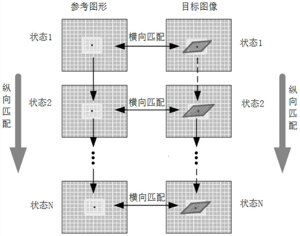
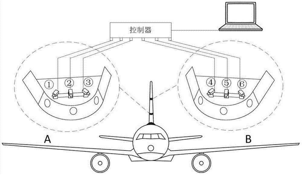
[0022] In a specific embodiment, a method for measuring the full-field deformation of a wing with a large inclination angle is provided, which can measure the full-field deformation of the wing during aircraft flight. In the method, the camera will take two cameras in the same area to form a group of binocular measurement systems, and one group of image sequences of the measured surface captured by the two cameras is regarded as a reference image sequence, and the other group is regarded as a target image sequence, each group of images is a state under a time sequence, and the prepared speckle is on the image, and then the following steps are performed:

[0023] S301: Calculating matching parameters between the reference image and the target image in the first state;

[0024] S302: Calculating matching parameters between the reference image in the i-th state and the reference image in the first state;

[0025] S303: Calculating matching parameters between the target image in ...


PUM


Abstract

The invention provides a measuring method for full field deformation of a large-dip-angle wing. According to the method, a binocular measurement system is formed by two cameras in one area photographed by a video camera, one of image sequences of to-be-tested surfaces respectively photographed by the two cameras is taken as a reference image sequence, the other image sequence is taken as a target image sequence, each group of images is under one time sequence, and speckles are processed on the images; vertical matching under respective time sequences is performed on the basis of horizontal matching in a first state, and performing horizontal matching for other states besides the first state; deformation displacement fields of the to-be-tested surfaces are reconstructed according to calculation results of matching parameters, calibration parameters of the cameras and a triangulation principle. The measuring method is a non-contact measuring method with a high matching success rate and has the advantage of high speckle matching speed as compared with conventional speckle matching methods.

Description

technical field [0001] The invention relates to the field of non-contact deformation measurement, in particular to a method for measuring the full-field deformation of a wing with a large inclination angle. Background technique [0002] The wing of a large aircraft deforms greatly in actual flight. Although a large number of simulation calculations have been carried out during design, it is still necessary to accurately measure its three-dimensional deformation data in actual flight experiments. At present, my country has started the design and manufacture of large passenger aircraft and transport aircraft, but the detection means for the wing of large aircraft during flight is still relatively scarce. The wing of a large aircraft bears a very large aerodynamic load during flight, and usually the wingtips of a large aircraft with a wingspan of 40 to 50 meters fluctuate more than 1 meter up and down during flight. The deformation of the wing is huge, and it is necessary to o...

Claims


Application Information

Patent Timeline
Patent Type & Authority Applications(China)
IPC IPC(8): G01B11/16
Inventor 梁晋魏斌千勃兴王立忠胡浩李磊刚郭楠
Owner XI AN JIAOTONG UNIV
Why Eureka
Try Eureka