Large-visual-field high-resolution optical system

An optical system and high-resolution technology, applied in the field of optical systems, can solve the problems of difficult design and processing of lens systems, unreachable, huge amount of information, etc., and achieve the effect of reducing difficulty and cost, small aperture, and good expansion performance

Active Publication Date: 2015-07-01
ZHANGJIAGANG ZHONGHE AUTOMATION TECH
View PDF4 Cites 7 Cited by
  • Summary
  • Abstract
  • Description
  • Claims
  • Application Information

AI Technical Summary

Problems solved by technology

[0003] Generally speaking, under the current technical conditions, there are three main technical difficulties in large-field high-resolution imaging: 1) The number of pixels on the current single-chip image sensor is far from reaching the 1 billion required by large-field high-resolution imaging order of magnitude; 2) From the perspective of optical design, due to the existence of aberrations, it is very difficult to design and process a lens system that matches the resolution of a 1 billion-pixel image sensor; 3) Due to the large field of view and high-resolution imaging, the The huge amount of information in photos puts forward very high real-time requirements for image transmission and image processing, which is still a major technical problem for the current technical level

Method used


Image

  • Large-visual-field high-resolution optical system
  • Large-visual-field high-resolution optical system
  • Large-visual-field high-resolution optical system

Examples


Embodiment Construction

[0034] In order to make the object, technical solution and advantages of the present invention clearer, the present invention will be further described in detail below in conjunction with the accompanying drawings and embodiments. It should be understood that the specific embodiments described here are only used to explain the present invention, not to limit the present invention.

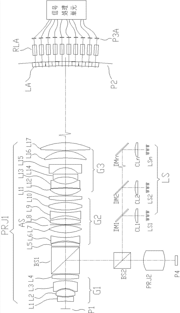
[0035] see figure 1 , which is a schematic structural diagram of the large-field-of-view high-resolution optical system provided by a preferred embodiment of the present invention. From the object plane P1 to the image plane P2, the large field of view high-resolution optical system sequentially includes a projection objective lens PRJ1, a split lens array LA, an imaging lens array PLA, an image sensor array P3A, and a signal processing unit. The signal processing unit is electrically Connected to the image sensor array P3A.

[0036] From the object plane P1 to the image plane P2, the projection ...


PUM


Abstract

The invention discloses a large-visual-field high-resolution optical system. The large-visual-field high-resolution optical system comprises an imaging lens array, an image sensor array, a signal processing unit, a projection objective and a division lens array. The projection objective is positioned between an object plane and a first image plane. Units in the three arrays are in one-to-one correspondence mapping relation. The division lens array is positioned close to the first image plane. The imaging lens array and the image sensor array are positioned on one side, away from the object plane P1, of the first image plane. The division lens array is positioned between the object plane and the first image plane and close to the first image plane. The imaging lens array is positioned between the first image plane and the image sensor array. The first image plane is divided into visual field arrays by the division lens array, the object plane is imaged to a light sensing face of the image sensor array by the imaging lens array, and the image sensor array collects an image information array. The signal processing unit processes the image information array in an image processing mode to acquire large-visual-field high-resolution computational images.

Description

technical field [0001] The invention relates to an optical system, in particular to a large-field-of-view high-resolution optical system. Background technique [0002] Large field of view high-resolution optical systems are widely used in fields such as biomedicine, aerial reconnaissance and topographic mapping. However, due to the mutual restriction between the field of view and the resolution, it is generally impossible to obtain a wide-format high-resolution image with only one exposure. If it is necessary to increase the width during high-resolution imaging, mechanical scanning is generally used. However, it takes a long time to scan and acquire a wide-format image, and there is a time interval between frames, so this method is only effective for static scenes. For some applications, such as large-scale continuous monitoring, while obtaining a large field of view, it is necessary to ensure that the detailed information of the target cannot be lost, and it must be compl...

Claims


Application Information

Patent Timeline
Patent Type & Authority Applications(China)
IPC IPC(8): G02B13/00G02B13/22
CPCG02B13/005G02B13/22
Inventor 刘鹏
Owner ZHANGJIAGANG ZHONGHE AUTOMATION TECH
Why Eureka
Try Eureka