Boarder weakening method of naked-eye 3D (three dimensional) splice display screen

A display splicing and splicing screen technology, which is applied in optics, instruments, optical components, etc., can solve the problems of adding complex circuits and optical path structures, increasing costs, unfavorable marketing, etc., and achieves a product that is conducive to market promotion, easy to implement, and low in price Effect

Active Publication Date: 2015-07-01
NINGBO VISION DISPLAY TECH
View PDF8 Cites 6 Cited by
  • Summary
  • Abstract
  • Description
  • Claims
  • Application Information

AI Technical Summary

Problems solved by technology

[0008] The purpose of the present invention is to solve the problem that the two methods used in the existing frame weakening need to add complex circuits and optical path structures, which lead to increased costs and are not conducive to market promotion, and provide a frame weakening method for naked-eye 3D display splicing screens

Method used


Image

  • Boarder weakening method of naked-eye 3D (three dimensional) splice display screen
  • Boarder weakening method of naked-eye 3D (three dimensional) splice display screen
  • Boarder weakening method of naked-eye 3D (three dimensional) splice display screen

Examples


specific Embodiment approach 1

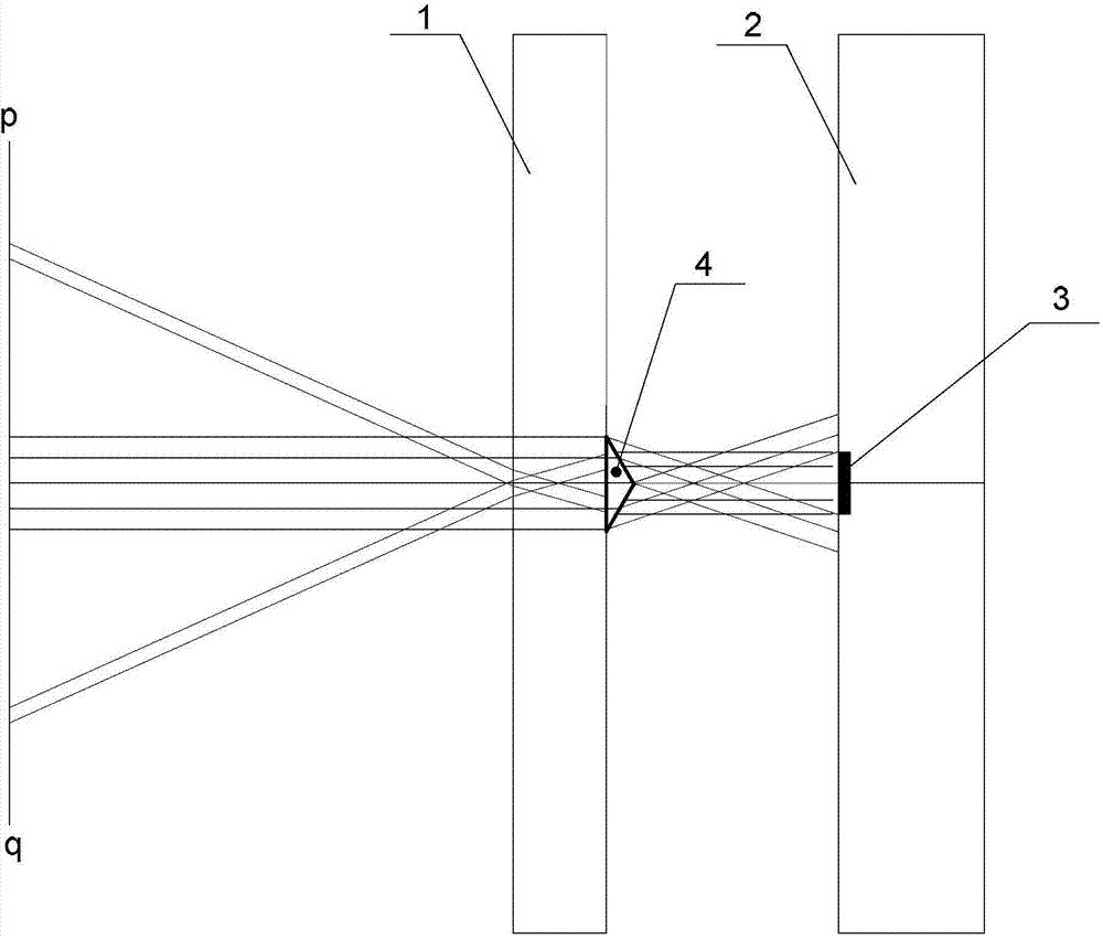
[0021] Specific implementation mode one: the following combination figure 1 Describe this embodiment, the frame weakening method of the naked-eye 3D display splicing screen described in this embodiment, the large-size display includes a front glass plate 1 with a grating film and a splicing screen 2, and the front glass plate 1 with a grating film is arranged on the splicing screen The front of the screen 2; there is a border 3 between every two unit screens of the splicing screen 2;

[0022] A triangular prism 4 is arranged on one side surface of the front glass plate 1 with a grating film, and the optical axis center of the triangular prism 4 and the geometric center of the frame 3 are at the same viewing level; 3 is 30% to 50% larger in width, and the length of the prism 4 is equal to the length of the frame 3, so that when viewing, the light reflected by the frame 3 is transferred to outside the visible area by the refraction of the prism 4, and the light near the frame 3 ...

specific Embodiment approach 2

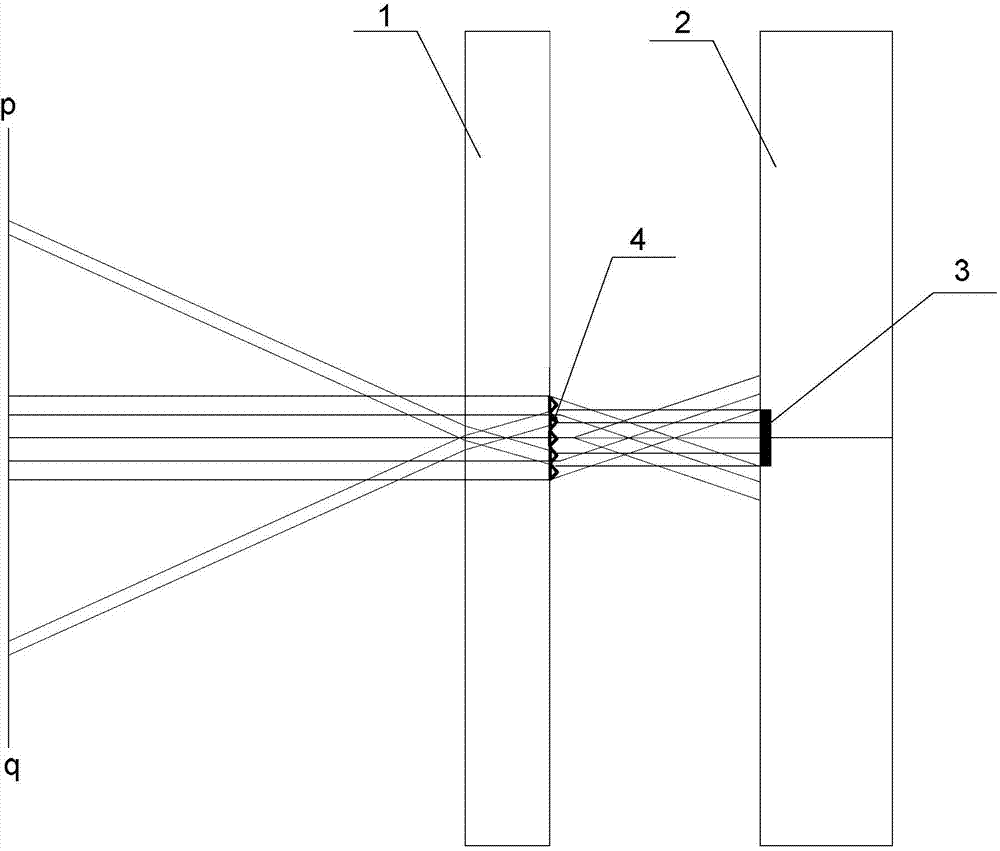
[0029] Specific implementation mode two: the following combination Figure 4 This embodiment will be described. This embodiment will further describe the first embodiment. One side of the front glass plate 1 with a grating film is provided with a triangular groove, and a triangular prism 4 is arranged in the groove.

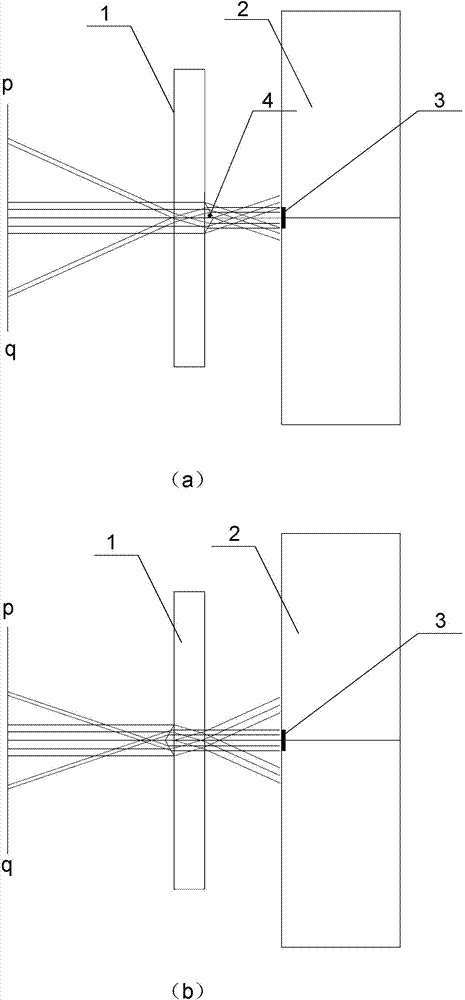
[0030] see Figure 4 (a), the triangular prism 4 is arranged on the near display screen side, Figure 4 The triangular prism 4 in (b) is arranged on the far display screen side.

[0031] This embodiment describes the concave structure, and this arrangement keeps the front glass plate 1 without protrusions inside and outside.

specific Embodiment approach 3

[0032] Specific implementation mode three: the following combination image 3 This embodiment will be described. This embodiment will further describe the first embodiment. The triangular prism 4 is protrudingly arranged on one side surface of the front glass plate 1 with a grating film.

[0033] see image 3 (a), the triangular prism 4 is arranged on the near display screen side, image 3 The triangular prism 4 in (b) is arranged on the far display screen side.


PUM


Abstract

The invention belongs to the technical field of 3D (three dimensional) display, discloses a boarder weakening method of a naked-eye 3D splice display screen and aims to solve the problem that the two conventional boarder weakening methods adopt complicated circuit and optical path structures, causing high cost; according to the technical scheme, the boarder weakening method includes that a large-size display comprises a front glass board with grating film and a splice screen, and between every two unit screens of the splice screen, a boarder is provided; a triple prism is arranged on the surface of one side of the glass board, and the optical axis center of the triple prism and the geometric center of the boarder are on the same viewing horizontal position; length of one side opposite to the point angle of the triple prism is greater 30%-50% than width of the boarder, and length of the triple prism is equal to that of the boarder, in this way, as watching, light rays reflected by the boarder are transmitted outside a visible range under reflection action of the triple prism, and light rays of display images around the boarder are reflected in eyes, so that the boarder between the unit screens is visually weakened, and the whole splice screen displays in a seamless display way. Besides, the triple prism can be replaced by a triple prism array.

Description

technical field [0001] The invention belongs to the technical field of stereoscopic display, and is especially aimed at the naked-eye 3D display splicing technology. The invention realizes the effect of weakening the splicing seam of the naked-eye 3D display splicing screen. Background technique [0002] Vision is the main source of information for human beings to perceive external objective events. It is the goal people have been pursuing to restore the real, clear and intuitive world through display devices. The development of display technology truly shows this process: from static to dynamic, from black and white Color, from SD to HD, from flat to stereoscopic. [0003] Larger screens are an inevitable trend in the development of display technology, especially stereoscopic display technology. The larger the size of the display, the stronger the stereoscopic effect, and therefore it is more popular in the market. However, limited by traditional display technology, super-...

Claims


Application Information

Patent Timeline
Patent Type & Authority Applications(China)
IPC IPC(8): G02B27/22G09F9/00
CPCG02B30/27G09F9/00
Inventor 虞志刚顾开宇
Owner NINGBO VISION DISPLAY TECH
Why Eureka
Try Eureka