Power battery module

A power battery and battery technology, which is applied in the direction of batteries, battery pack components, secondary batteries, etc., can solve the unfavorable automatic production of power battery modules, increase the production cost of power battery modules, and the battery combination method cannot be freely expanded. , to achieve the effect of reducing maintenance cost and time, light weight, and eliminating messy structure

Active Publication Date: 2017-07-04
BYD CO LTD
View PDF4 Cites 0 Cited by
  • Summary
  • Abstract
  • Description
  • Claims
  • Application Information

AI Technical Summary

Problems solved by technology

[0002] In related technologies, power battery modules mostly use multi-plate or upper and lower shell assembled battery housing components. Although this structure can better protect the battery, due to the structural limitations of the multi-plate structure and the upper and lower shell structure, The battery combination method cannot be freely expanded. When the battery combination method changes, it needs to be redesigned and developed, which greatly increases the time and cost of project development. At the same time, the above two structures are not conducive to the automatic production of power battery modules. Increase the production cost of the power battery module, making the product lose its competitive advantage

Method used


Image

  • Power battery module
  • Power battery module
  • Power battery module

Examples


Embodiment Construction

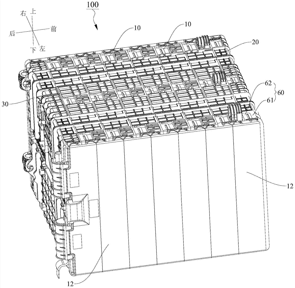
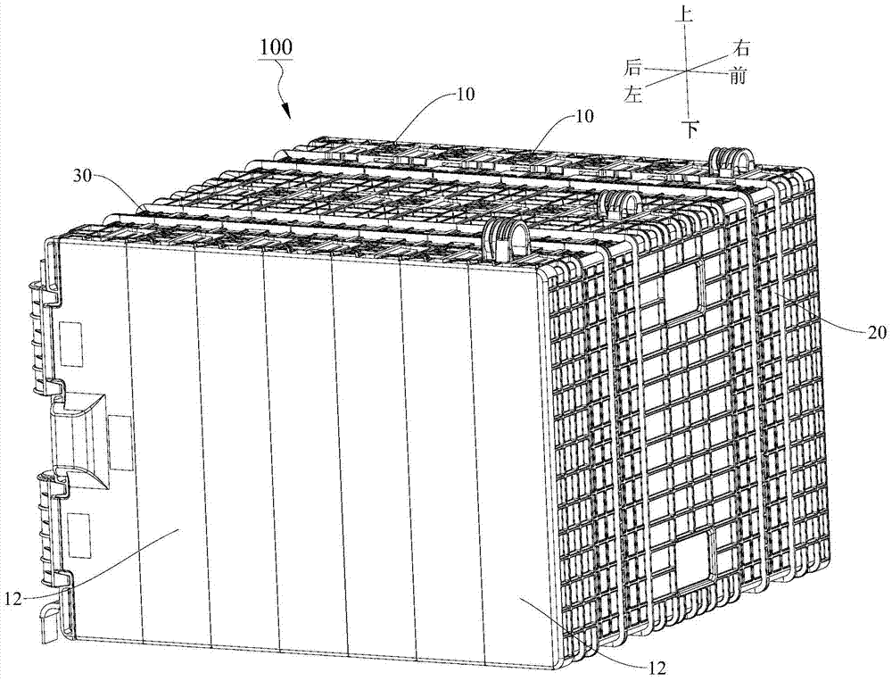
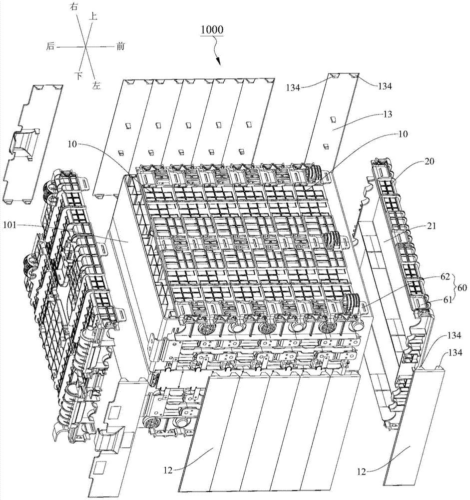
[0061] Embodiments of the present invention are described in detail below, examples of which are shown in the drawings, wherein the same or similar reference numerals designate the same or similar elements or elements having the same or similar functions throughout. The embodiments described below by referring to the figures are exemplary and are intended to explain the present invention and should not be construed as limiting the present invention.

[0062] In describing the present invention, it should be understood that the terms "center", "longitudinal", "transverse", "length", "width", "thickness", "upper", "lower", "front", " Orientation or position indicated by "back", "left", "right", "vertical", "horizontal", "top", "bottom", "inner", "outer", "clockwise", "counterclockwise", etc. The relationship is based on the orientation or positional relationship shown in the drawings, and is only for the convenience of describing the present invention and simplifying the descrip...


PUM


Abstract

The invention discloses a power battery module, comprising: a battery containing assembly, a battery pack, a power connector, a power connecting line, a harness buckle and a signal collecting assembly, the battery containing assembly includes a plurality of partitions, and the adjacent partitions are detachably connected to each other. The harness buckle includes a body with a wire slot. The signal acquisition component includes a substrate, a signal acquisition line, a signal acquisition element and a signal acquisition terminal. The signal acquisition line is composed of a sheet-shaped conductive metal piece laid on the substrate. The signal acquisition element is arranged on the substrate and connected to the signal acquisition line. The collection terminal is arranged on the substrate and has a first end connected with the signal collection line and a second end electrically connected with the power connector. According to the power battery module of the embodiment of the present invention, the battery containing component can conveniently expand the number of batteries and the connection form according to the actual demand of the customer for the power battery module.

Description

technical field [0001] The invention relates to the field of batteries, in particular to a power battery module. Background technique [0002] In related technologies, power battery modules mostly use multi-plate or upper and lower shell assembled battery housing components. Although this structure can better protect the battery, due to the structural limitations of the multi-plate structure and the upper and lower shell structure, The battery combination method cannot be freely expanded. When the battery combination method changes, it needs to be redesigned and developed, which greatly increases the time and cost of project development. At the same time, the above two structures are not conducive to the automatic production of power battery modules. The production cost of the power battery module is increased, and the product loses its competitive advantage. Contents of the invention [0003] The present invention aims to solve one of the above-mentioned technical proble...

Claims


Application Information

Patent Timeline
Patent Type & Authority Patents(China)
IPC IPC(8): H01M2/02H01M2/10H01M10/48H01M50/204H01M50/209H01M50/244H01M50/258H01M50/262H01M50/269H01M50/291H01M50/298H01M50/50H01M50/503H01M50/519H01M50/522H01M50/526H01M50/529H01M50/569
CPCH01M10/04H01M10/48H01M50/24H01M50/50H01M50/291H01M50/503H01M50/569H01M10/482H01M50/209H01M50/298H01M50/522H01M50/519H01M50/262H01M10/658H01M50/526H01M10/425H01M2220/20Y02E60/10H01M50/20H01M2010/4271H01M2010/4278
Inventor 朱燕彭青波卢甲张雪峰刘伟黄雁鲁志佩朱建华
Owner BYD CO LTD
Why Eureka
Try Eureka