Auxiliary tool for replacing insulator and method for replacing insulator using the same

A technology of auxiliary tools and insulators, applied in the direction of overhead lines/cable equipment, etc., can solve the problems of line tripping, large conductor depression force, and large conductor depression force, etc., to avoid tripping accidents, ensure domestic electricity consumption, The effect of the overall structure is simple

Inactive Publication Date: 2017-03-01
STATE GRID SICHUAN PENGXI COUNTY POWER SUPPLY CO LTD
View PDF7 Cites 0 Cited by
  • Summary
  • Abstract
  • Description
  • Claims
  • Application Information

AI Technical Summary

Problems solved by technology

[0002] The insulators on the straight poles on the hillside are subjected to a large downward force from the wires. At present, when replacing the damaged insulators on the straight poles on the hillside, the workers use their shoulders to lift the wires, and then replace the damaged insulators. The downward pressure force is relatively large, and the operators are easily injured when carrying the wires on their shoulders, which makes the operators unwilling to replace the insulators on the straight poles on the hillside
If the damaged insulator is not replaced in time, it is easy to be struck by lightning and cause a line trip accident, which will affect people's daily electricity consumption

Method used


Image

  • Auxiliary tool for replacing insulator and method for replacing insulator using the same

Examples


Embodiment 1

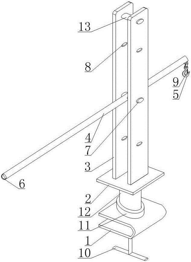
[0021] Such as figure 1 As shown, the auxiliary tool for insulator replacement includes a base 1, a bottom plate 2, a support limit plate 3, a lever 4, a hook 5, a pull ring 6 and a positioning shaft 7, wherein the base 1 of this embodiment is a U-shaped structure, and its The U-shaped opening is located on one side to form a bayonet, and the bottom plate 2 is fixed above the base 1 . In the present embodiment, the supporting limiting plate 3 adopts a vertically arranged rectangular plate, and the number of supporting limiting plates 3 is two. The lever 4 in this embodiment is provided with through holes that run through its opposite sides. The positioning shaft 7 is horizontally arranged and passes through the through holes on the lever 4. The two ends of the positioning shaft 7 are respectively connected with two support limit plates 3. The hooks 5 and the pull ring 6 are connected to the two ends of the lever 4 respectively. In the specific setting of this embodiment, the...

Embodiment 2

[0024] This embodiment makes the following further limitations on the basis of Embodiment 1: the support limiting plate 3 of this embodiment is provided with a plurality of positioning holes 8 passing through its opposite side walls, wherein the plurality of positioning holes 8 The vertical direction of the limiting plate 3 is equidistantly arranged, the number of positioning holes 8 on the two supporting limiting plates 3 is the same and the positions correspond to each other, and the positioning shaft 7 is connected with the supporting limiting plate 3 after passing through the positioning holes 8. The positioning shaft 7 of this embodiment is realized by using bolts, the positioning shaft 7 passes through the positioning holes 8 of the two support limit plates 3, and a nut is sleeved on the positioning shaft 7, and then the positioning shaft 7 is fixed on the support limit plate 3 superior. When the auxiliary tool of this embodiment is applied, the positioning shaft 7 can p...

Embodiment 3

[0026] This embodiment makes the following further limitations on the basis of Embodiment 1 or Embodiment 2: This embodiment also includes a limiting piece 9, one end of the limiting piece 9 is hinged to the connecting end of the hook 5, and the other end is arranged on the hook. 5 and contact with the side where the free end of the hook 5 is located in the half-closed area of ​​the hook 5 . Wherein, the connecting end of the hook 5 is specifically an end of the hook 5 connected to the lever 4, and the free end of the hook 5 is a bent end thereof. When the auxiliary tool of this embodiment is used, the wires leading into the hook 5 are limited by the limiting sheet 9. After the damaged insulator is replaced, the operator on the pole presses down the limiting sheet 9 to take out the wires.


PUM


Abstract

The invention discloses an auxiliary tool for insulator replacement. The auxiliary tool comprises a base, a bottom plate, two bearing limit boards, a lever, hooks, pull rings and a positioning shaft, a bayonet provided with an opening in one side is arranged in the base, and the bottom plate is fixed above the base; the bearing limit boards are parallely arranged with lower ends fixed on the upper end face of the bottom plate; a through hole penetrating two sides of the lever is arranged in the lever, the positioning shaft is horizontally arranged and penetrates the through hole in the lever, two ends of the positioning shaft are respectively connected with the bearing limit boards, and the hooks and the pull rings are respectively connected to two ends of the lever. The invention further discloses a method for replacing an insulator with the above auxiliary tool. The auxiliary tool is convenient to operate, timesaving and laborsaving during replacement of the damaged insulator, an operator carrying a lead on the shoulder can be avoided, injury to the operator by pushing acting force of the lead can be avoided, and influence to work enthusiasm of the operator prone to be injured can be eliminated.

Description

technical field [0001] The invention relates to the field of operation, maintenance, repair and construction of power distribution lines, in particular to an auxiliary tool for replacing insulators and a method for replacing insulators using the tool. Background technique [0002] The insulators on the straight poles on the hillside are subjected to a large downward force from the wires. At present, when replacing the damaged insulators on the straight poles on the hillside, the workers use their shoulders to lift the wires, and then replace the damaged insulators. The downward pressure force of the wire is relatively large, and the operator is easily injured when carrying the wire on his shoulder, which makes the operator unwilling to replace the insulator on the linear rod at the hillside. If the damaged insulator is not replaced in time, it is easy to be struck by lightning and cause a line trip accident, which will affect people's daily electricity consumption. Content...

Claims


Application Information

Patent Timeline
Patent Type & Authority Patents(China)
IPC IPC(8): H02G1/02
Inventor 吕宗永蒋庆俊田洪军
Owner STATE GRID SICHUAN PENGXI COUNTY POWER SUPPLY CO LTD
Why Eureka
Try Eureka