Self-locking power switch

A power switch and self-locking technology, which is applied in the direction of battery disconnection circuit, charging station for charging mobile devices, current collectors, etc. It is suitable for problems such as long-distance transportation of electronic equipment to achieve the effect of reducing power consumption

Active Publication Date: 2015-07-01
NINGBO SAGEREAL COMM
View PDF7 Cites 3 Cited by
  • Summary
  • Abstract
  • Description
  • Claims
  • Application Information

AI Technical Summary

Problems solved by technology

[0005] Although the above-mentioned patent can reduce the power consumption of the battery, it cannot effectively ensure that the electronic device and the pow

Method used


Image

  • Self-locking power switch

Examples


Embodiment Construction

[0029] The present invention will be further described below in conjunction with the accompanying drawings and specific embodiments, but not as a limitation of the present invention.

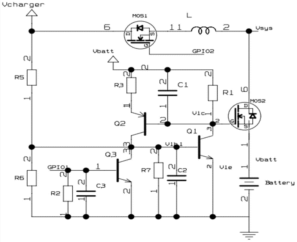
[0030] In order to solve many defects in the prior art, because the battery power of the electronic device is exhausted, the electronic device may not be turned on, and it is considered as a faulty device and returned, thus wasting a lot of transportation costs and time costs, etc., the present invention provides A power switch with a self-locking function, the power switch is mainly composed of a first MOS tube MOS 1 , the second MOS tube MOS 2 , the first triode Q 1 , the second triode Q 2 , the third triode Q 3 , Charger V charger port and battery and many other components, among them, the system power supply V sys Can be charged by the charger through the first MOS tube MOS 1 supply, and also by the battery through the second MOS tube MOS 2 supply, the first transistor Q 1 and the se...


PUM


Abstract

The invention relates to the technical field of circuit designing, in particular to a self-locking power switch comprising a first MOS (metal oxide semiconductor) transistor, a second MOS transistor, a first triode, a second triode, a third triode, a charger, a battery and other components. System power of an electronic device can be provided through the first MOS transistor by a charger and can also be provided through the second MOS transistor by the battery; a self-locking circuit composed of the first triode and the second triode is capable of effectively controlling reliable connection or disconnection of the electronic device and the battery, power consumption of the battery is maximally reduced, and the self-locking power switch is applicable to various applications, such as remote transporting of electronic equipment.

Description

technical field [0001] The invention relates to the technical field of circuit design, in particular to a power switch with a self-locking function. Background technique [0002] With the development of society, more and more electronic devices, such as mobile phones, pads, game consoles and other electronic products, have non-detachable power supplies, and users can directly charge the power supply and use the electronic devices. [0003] However, products such as electronic equipment have to go through a lot of time and go through various transportation processes from the factory to the user. On the one hand, it is not safe to transport electronic equipment with power on, and it will consume electricity; on the other hand, when the electronic equipment reaches the customer, it may be exhausted due to the power exhaustion, which may cause the electronic equipment to fail to turn on, and it is considered to be a faulty equipment. This wastes a lot of transportation costs an...

Claims


Application Information

Patent Timeline
IPC IPC(8): H02J7/00
CPCH02J7/0027H02J7/0032
Inventor 常爱民齐利敏周美芬宁丽芳范超群
Owner NINGBO SAGEREAL COMM
Why Eureka
Try Eureka