
Variable displacement swash-plate compressor

A variable type, swash plate type technology, applied in liquid variable volume machinery, mechanical equipment, machine/engine, etc., can solve the problems of unstable tilt angle and the influence of the refrigerant pulsation of the actuator.

Active Publication Date: 2015-07-01
TOYOTA IND CORP
View PDF7 Cites 3 Cited by
  • Summary
  • Abstract
  • Description
  • Claims
  • Application Information

AI Technical Summary

Problems solved by technology

Therefore in this compressor, the actuator is susceptible to the pulsation of the discharged refrigerant
Therefore, in this compressor, the inclination angle is unstable, and it is difficult to operate with an appropriate discharge capacity according to the operating conditions of the vehicle on which it is mounted.

Method used


Image

  • Variable displacement swash-plate compressor
  • Variable displacement swash-plate compressor
  • Variable displacement swash-plate compressor

Examples


no. 1 approach

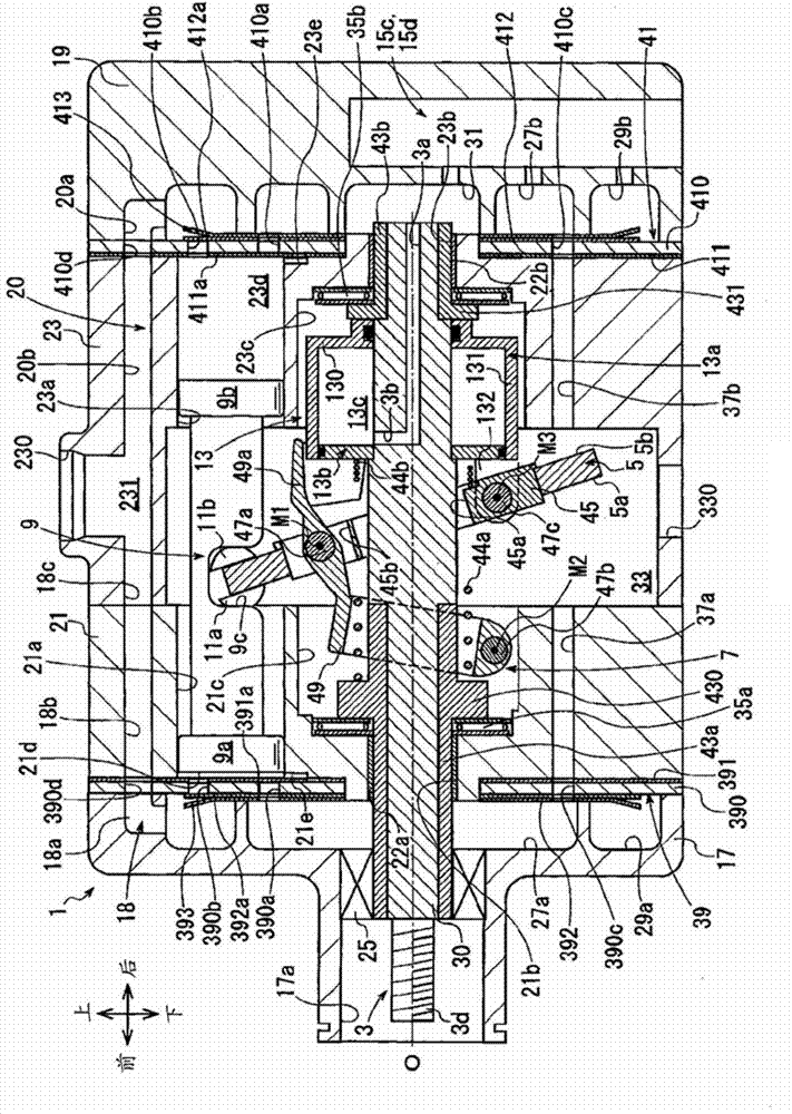
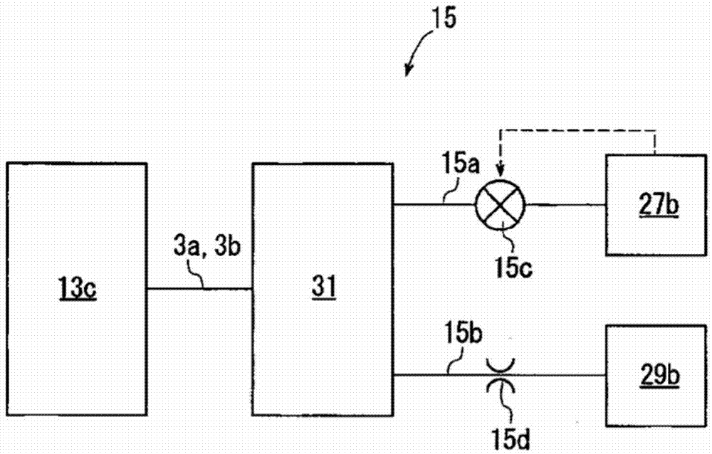
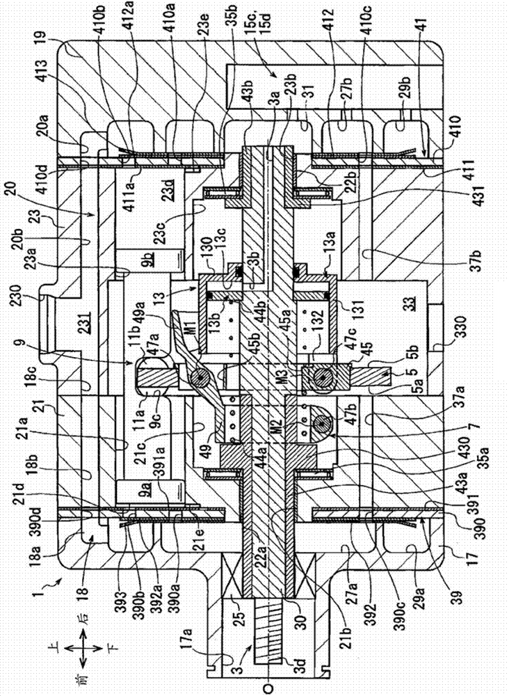
[0023] Such as figure 1 As shown, the compressor of the first embodiment includes: a housing 1, a drive shaft 3, a swash plate 5, a connecting rod mechanism 7, a plurality of pistons 9, a pair of sliding shoes 11a, 11b, an actuator 13 and figure 2 The control mechanism 15 is shown.

[0024] Such as figure 1 As shown, the housing 1 has: a front housing 17 located on the front side of the compressor; a rear housing 19 located on the rear side of the compressor; a first cylinder block located between the front housing 17 and the rear housing 19 21. The second cylinder block 23; and the first valve forming plate 39 and the second valve forming plate 41.

[0025] A protrusion 17 a protruding forward is formed on the front case 17 . A shaft seal 25 is arranged in this projection 17a. In addition, a first suction chamber 27 a and a first discharge chamber 29 a are formed in the front housing 17 . The first suction chamber 27 a is located radially inside the front housing 17 . ...

no. 2 approach

[0098] Such as Figure 4 As shown, the compressor of the second embodiment has: a housing 201, a drive shaft 203, a swash plate 205, a connecting rod mechanism 207, a plurality of pistons 209, a plurality of pairs of sliding shoes 211a, 211b, an actuator 213 and Figure 5 The control mechanism 16 is shown.

[0099] Such as Figure 4 As shown, the housing 201 has: a front housing 217 located at the front side of the compressor, a rear housing 219 located at the rear side of the compressor, a cylinder block 221 located between the front housing 217 and the rear housing 219 and valves Plate 223 is formed.

[0100] The front housing 217 has a front wall 217a extending in the vertical direction of the compressor on the front side, and a peripheral wall 217b integrated with the front wall 217a and extending from the front of the compressor toward the rear. The front case 217 has a substantially cylindrical shape with a bottom formed by the front wall 217a and the peripheral wall ...


PUM


Abstract

This variable displacement swash-plate compressor comprises: a housing in which an intake chamber, a discharge chamber, a swash-plate chamber, and a cylinder bore are formed; a drive shaft rotatably supported by the housing; a swash plate that is rotatable in the swash-plate chamber by the rotation of the drive shaft; an actuator that can change the tilt angle of the swash plate; and a control mechanism that controls the actuator. A pressure adjustment chamber is formed in the housing. The actuator includes: a fixed body; a movable body that can change the tilt angle of the swash plate; and a control pressure chamber that moves the movable body. The control mechanism includes: a control passage that links the discharge chamber, the pressure adjustment chamber, and the control pressure chamber; and a control valve that, by adjusting the degree of opening of the control passage, can change the pressure in the control pressure chamber so that the movable body can be moved. A refrigerant in the discharge chamber flows into the control pressure chamber via the pressure adjustment chamber. The pressure adjustment chamber functions as a muffler that reduces the pulsation of the refrigerant.

Description

technical field [0001] The present invention relates to variable capacity swash plate compressors. Background technique [0002] Patent Document 1 discloses a conventional variable capacity swash plate compressor (hereinafter referred to as a compressor). In this compressor, a casing is formed by a front casing, a cylinder block, and a rear casing. A suction chamber and a discharge chamber are respectively formed in the front case and the rear case. In addition, a control pressure chamber is formed in the rear case. [0003] A swash plate chamber, a plurality of cylinder bores, and a main shaft through hole are formed in the cylinder block. Each cylinder bore is comprised of the 1st cylinder bore formed in the rear side of a cylinder block, and the 2nd cylinder bore formed in the front side of a cylinder block. A main shaft through hole is formed on the rear side of the cylinder block, and communicates with the swash plate chamber and the control pressure chamber. [00...

Claims


Application Information

Patent Timeline
Patent Type & Authority Applications(China)
IPC IPC(8): F04B27/14F04B27/08
CPCF04B27/12F04B27/18F04B11/0091F04B27/1054F04B2027/1818F04B2027/1831
Inventor 仲井间裕之山本真也铃木隆容太田雅树本田和也西井圭山崎佑介
Owner TOYOTA IND CORP
Learn More