Profile cutting machine

A cutting machine and profile technology, which is applied in the direction of grinding workpiece supports, grinding machines, metal processing equipment, etc., can solve the problems of inaccurate positioning of profiles, flawed cutting accuracy, and prone to deflection, etc., and achieves exquisite device structure settings and high work efficiency. High, the effect of avoiding accidental injury

Active Publication Date: 2017-11-17
CHAOHU HAIFENG DOORS & WINDOWS
View PDF7 Cites 0 Cited by
  • Summary
  • Abstract
  • Description
  • Claims
  • Application Information

AI Technical Summary

Problems solved by technology

[0004] At present, there are various problems in the traditional profile cutting machine, such as the positioning of the profile is not accurate enough, the positioning is not stable, and it is prone to deflection during cutting, which affects the cutting effect. Many of them still use the cutter-style cutting method. Not only is it time-consuming and laborious, but there are also certain flaws in the cutting accuracy.

Method used


Image

  • Profile cutting machine
  • Profile cutting machine
  • Profile cutting machine

Examples


Embodiment Construction

[0019] The present invention will be described in further detail below according to the drawings and embodiments.

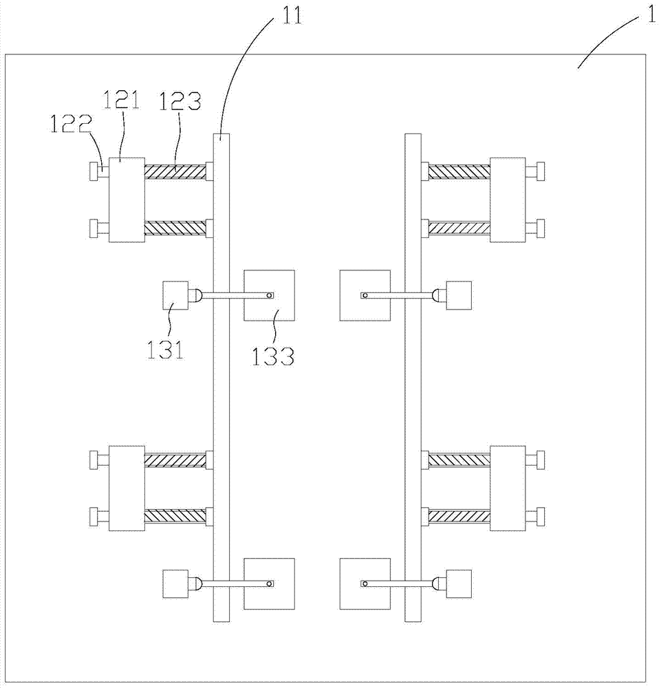
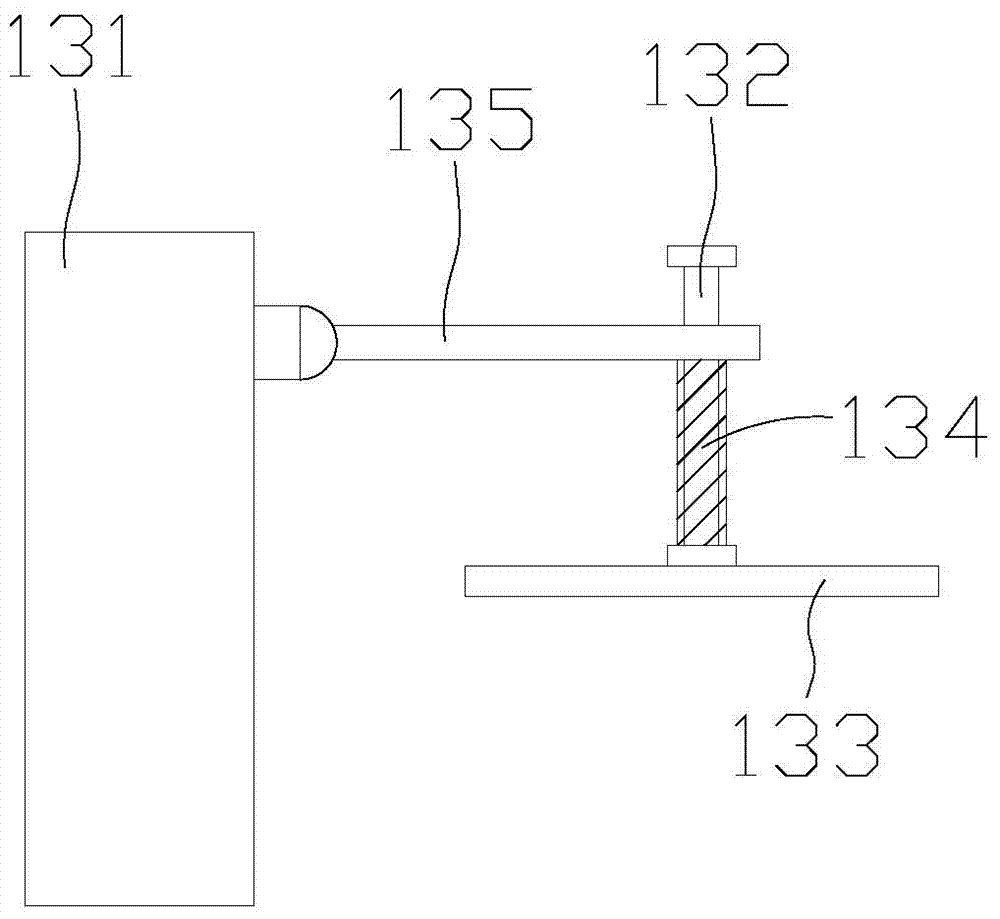
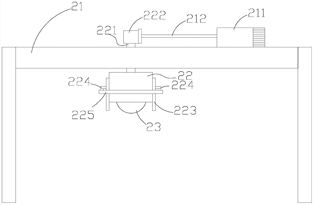
[0020] figure 1 It is a schematic diagram of the top view structure of the positioning device of the profile cutting machine of the present invention, figure 2 It is a structural schematic diagram of the vertical positioning mechanism of the present invention, image 3 It is a structural schematic diagram of the cutting device of the profile cutting machine of the present invention, Figure 4 It is a schematic sectional view of the cutting device of the profile cutting machine of the present invention, referring to Figure 1-Figure 4 According to the present invention, the profile cutting machine includes a positioning device and a cutting device, and the cutting device is located downstream of the positioning device.

[0021] Wherein, the positioning device includes: an operating table 1, two positioning plates 11, a plurality of horizontal positioning mecha...


PUM


Abstract

The invention discloses a section steel cutter. The section steel cutter comprises a positioning device and a cutting device, wherein the cutting device is arranged at the downstream of the positioning device; the positioning device comprises an operating platform, two positioning plates, multiple horizontal positioning mechanisms, and multiple vertical positioning mechanisms; the positioning plates are symmetrically arranged on the operating platform in parallel, and the multiple horizontal positioning mechanisms are respectively arranged at the outer sides of the positioning plates; the cutting device comprises a rack, a protection shell, a cutting wheel arranged in the protection shell, a cutting wheel fixing plate, a cutting wheel drive motor and a driving belt pulley; an opening is formed at the bottom of the protection shell, a sliding groove is formed in the rack, a sliding block is arranged at the top of the protection shell and penetrates through the sliding groove, a retaining bracket is arranged at the top of the sliding block, an actuating cylinder is arranged on the rack, and the retaining bracket is fixed by the push rod of the actuating cylinder. The section steel cutter has the beneficial effects that the accuracy is ensured when the section steel is cut, the cutting effect is good, and the operating efficiency is relatively high.

Description

technical field [0001] The invention relates to a cutting machine, especially a profile cutting machine. Background technique [0002] The profile cutting machine is suitable for sawing various special-shaped metals such as aluminum, aluminum alloy, copper, copper alloy, non-metallic plastic, and carbon fiber. It is especially suitable for aluminum doors and windows, photo frames, plastic steel, bakelite, aluminum extrusions, paper tubes, and profiles. Sawing; hand-held pressure sawing material, material is not easy to deform, low loss; sawing angle is precise; small vibration, low noise; simple operation, high efficiency, can be single or multiple sawing together. [0003] The profile cutting machine is powered by a single-phase AC series motor, and cuts metal tools by driving the flat grinding wheel through the transmission mechanism. It has the advantages of safety, reliability, low labor intensity, high production efficiency, and smooth cutting surface. It is suitable fo...

Claims


Application Information

Patent Timeline
Patent Type & Authority Patents(China)
IPC IPC(8): B24B41/06B24B27/06
CPCB24B27/06B24B41/06
Inventor 李国方俊
Owner CHAOHU HAIFENG DOORS & WINDOWS
Why Eureka
Try Eureka