Power take-off wheel

A power wheel and wheel hub technology, applied in the direction of wheels, control devices, transportation and packaging, etc.

Inactive Publication Date: 2015-07-08
贺和平
View PDF5 Cites 0 Cited by
  • Summary
  • Abstract
  • Description
  • Claims
  • Application Information

AI Technical Summary

Problems solved by technology

[0003] The purpose of the present invention is to solve the problem of how to use the interaction force between the wheel and the road surface to

Method used


Image

  • Power take-off wheel
  • Power take-off wheel
  • Power take-off wheel

Examples


Embodiment Construction

[0021] The power take-off wheel consists of the following components:

[0022] a. Wheel frame

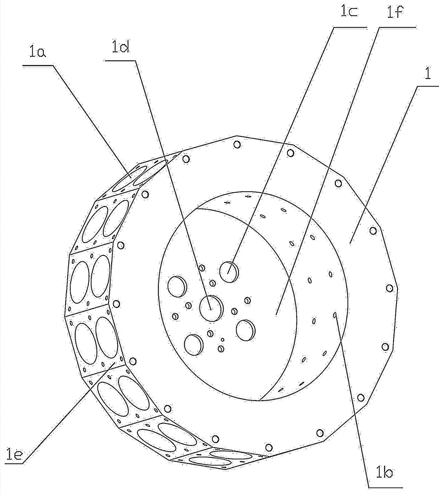
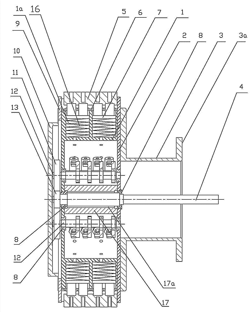
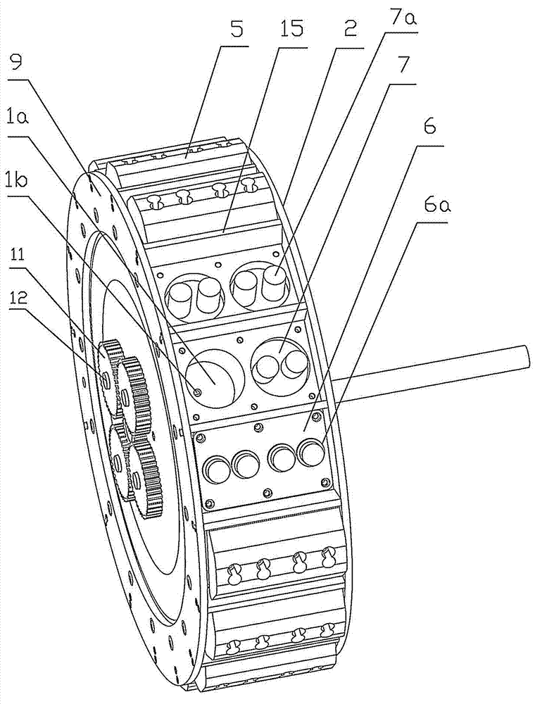
[0023] Such as figure 1 and figure 2 As shown, the wheel frame includes a hub 1, and the center of the hub 1 is provided with a cylindrical cavity 1f. The hub 1 is provided with 16 planar platforms 1e connected end to end, and the planar platforms 1e form a closed polygonal ring. A pair of power cylinders 1a are arranged on each flat platform 1e, and an oil hole 1b is arranged at the bottom of each power cylinder 1a. An output shaft hole 1d coaxial with the hub 1 is provided on the side wall of the cavity 1f, and four rotating shaft holes 1c are evenly distributed on the side wall of the cavity 1f. One side of the hub 1 is connected to the rim 9, and the other side is connected to the rim cover 2, and the rim cover 2 is provided with connecting holes corresponding to the output shaft hole 1d and the rotating shaft hole 1c respectively. Sixteen partitions 15 connected to th...


PUM


Abstract

The invention relates to a power take-off wheel. The power take-off wheel is characterized in that a wheel carrier comprises a hub (1), a group of power cylinders (1a) are uniformly distributed on the hub (1), one side of the hub (1) is connected with a rim (9), the other side of the hub (1) is connected with a rim cover plate (2), one side of the hub (1) is connected with a flange holder (3), two ends of the flange holder (3) are each provided with a flange plate (3a), the flange plate (3a) at one end of the flange holder (3) is connected with the hub (1), and the hub (1) is connected with a kinetic energy recovery device and a kinetic energy conversion output device. After the technical scheme is adopted, surplus kinetic energy generated during downhill running of an automobile is effectively utilized, so that the energy utilization ratio is improved, and meanwhile, abrasion of an automobile braking system is reduced.

Description

technical field [0001] The invention relates to a power generation device using wheels, in particular to a power taking wheel that uses the force of the wheels on the road surface to generate electricity when the vehicle is running. Background technique [0002] Low-carbon environmental protection, energy saving and emission reduction are what all countries in the world are trying to do, and automobile exhaust emissions are a problem that every country faces. Various automobile companies have also made corresponding achievements in this regard. Sun energy, parking and flameout, etc. When modern automobiles are damped, the method adopted is to maintain the stability of the vehicle body through the elastic damping of the suspension system on the vehicle body. From a mechanical point of view, the essence of vibration is the process of releasing and converting capabilities. Shock-absorbing purpose, however wasted energy. The present invention makes relevant attempts and resear...

Claims


Application Information

Patent Timeline
IPC IPC(8): B60B19/00B60K25/08
Inventor 贺和平贺云鹏贺云飞
Owner 贺和平
Why Eureka
Try Eureka