An underground gasification nozzle
An underground gasification and nozzle technology, applied in coal gasification, underground mining, construction, etc., can solve the problems affecting industrialization demand, open flame on the outer wall of the nozzle and pitting of burning coal particles, etc., to improve service life, prevent pitting, improve The effect of gas quality
- Summary
- Abstract
- Description
- Claims
- Application Information
AI Technical Summary
Problems solved by technology
Method used
Image
Examples
Embodiment 1
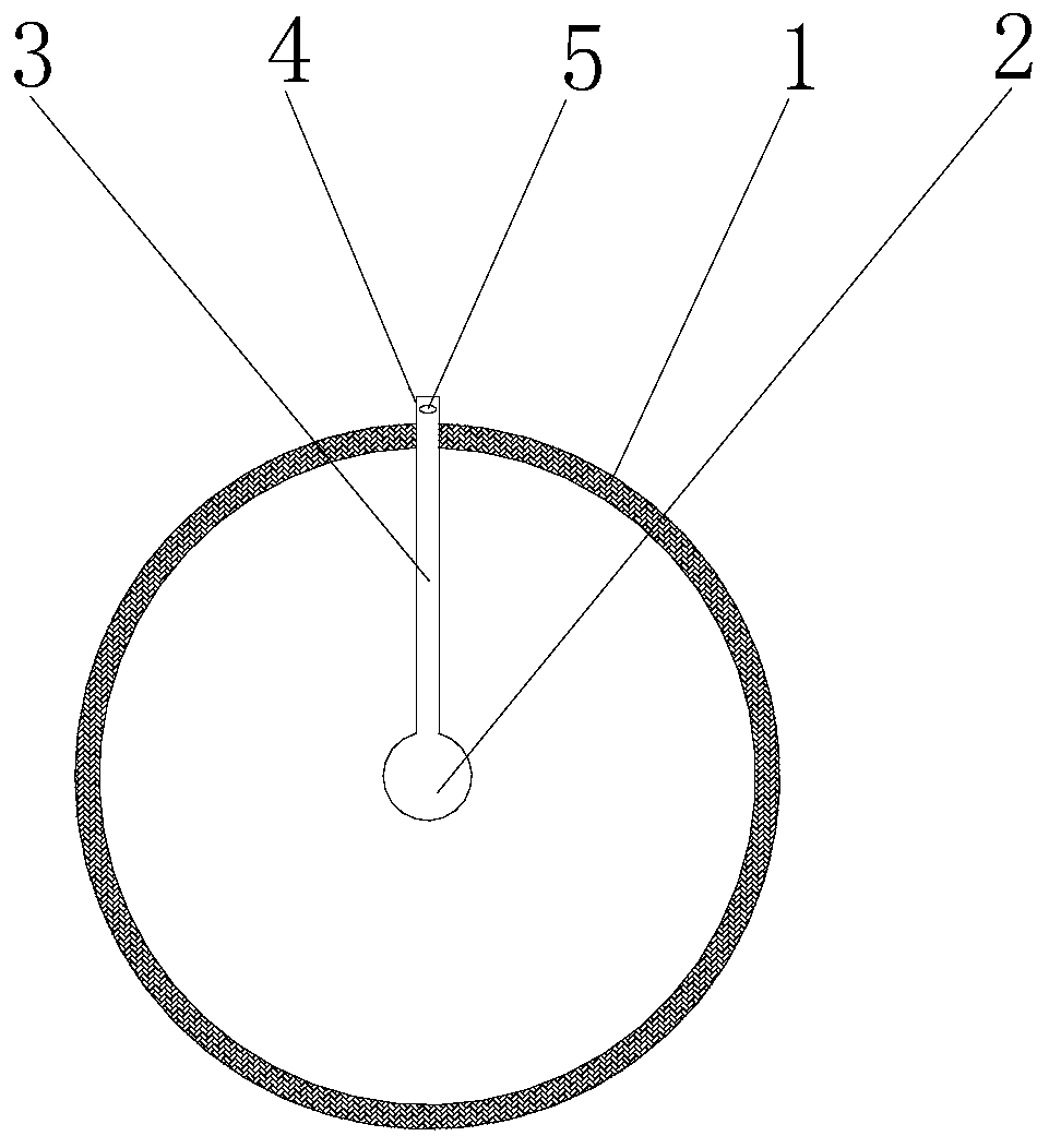
[0051] like figure 1 and figure 2 As shown, an underground gasification nozzle provided by Embodiment 1 of the present invention includes an outer pipe body 1, a main water pipe 2 is arranged inside the outer pipe body 1; a shunt pipe 3 connected to the main water pipe 2, and the shunt pipe 3 is provided with an extension The water outlet 4 of the outer wall of the outer pipe body 1; wherein, the water outlet 4 is a tubular structure; the top of the water outlet 4 is closed, and a first water outlet 5 is arranged on the side wall of the top of the water outlet 4; the water outlet of the first water outlet 5 is biased toward The axial direction of the outer tubular body 1 forms any angle between 45° and 90° with the axial direction of the outer tubular body 1 .
[0052] This structural setting can make the water flow sprayed out of the first water outlet hole 5 contact the outer surface of the outer wall of the outer pipe body 1 as soon as possible, ensure the water cooling o...
Embodiment 2
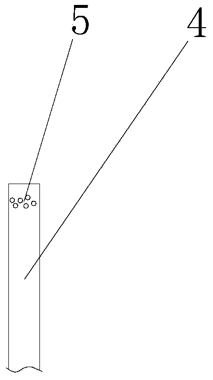
[0054] The main difference between the second embodiment of the present invention and the first embodiment of the present invention is that a plurality of first water outlet holes 5 are arranged on the top side wall of the water outlet part 4; image 3 As shown, the water outlet direction of each first water outlet hole 5 deviates from the axial direction of the outer tube body 1 and forms any angle between 45° and 90° with the axial direction of the outer tube body 1 . The other structures of the second embodiment are basically the same as those of the first embodiment. For details, reference may be made to the statement of the first embodiment above, and details are not repeated here.
Embodiment 3
[0056] The main difference between the third embodiment of the present invention and the first embodiment of the present invention is that the three branch pipes 3 connected by the main water pipe 2, such as Figure 4 As shown, each branch pipe 3 is provided with a water outlet 4 protruding from the outer wall of the outer pipe body 1; wherein, the water outlet 4 is a tubular structure; the top of the water outlet 4 is closed, and a first water outlet is arranged on the top side wall of the water outlet 4 Hole 5; the water outlet direction of the first water outlet hole 5 is biased toward the axial direction of the outer tube body 1 and forms any angle between 45° and 90° with the axial direction of the outer tube body 1 .
[0057] As another option, the main water pipe 2 can also be connected to two, four or five branch pipes 3, and a plurality of first water outlet holes 5 can also be arranged on the top side wall of the water outlet part 4.
[0058] The other structures of ...
PUM
 Abstract
Description
Claims
Application Information
 - R&D
- Intellectual Property
- Life Sciences
- Materials
- Tech Scout
- Unparalleled Data Quality
- Higher Quality Content
- 60% Fewer Hallucinations
Browse by: Latest US Patents, China's latest patents, Technical Efficacy Thesaurus, Application Domain, Technology Topic, Popular Technical Reports.
© 2025 PatSnap. All rights reserved.Legal|Privacy policy|Modern Slavery Act Transparency Statement|Sitemap|About US| Contact US: help@patsnap.com


