Compressor valve and compressor

A technology for compressors and valve plates, which is applied in the field of compressors, and can solve problems such as backflow of gas in the casing, and achieve the effects of smooth gas discharge, reduced energy consumption, and increased cross-sectional area of ​​exhaust flow

Active Publication Date: 2017-03-01
GREE ELECTRIC APPLIANCES INC +1
View PDF6 Cites 0 Cited by
  • Summary
  • Abstract
  • Description
  • Claims
  • Application Information

AI Technical Summary

Problems solved by technology

[0003] Aiming at the above-mentioned problem of housing gas backflowing into the cylinder cavity, the purpose of the present invention is to provide a new compressor valve plate and a compressor including the compressor valve plate.

Method used


Image

  • Compressor valve and compressor
  • Compressor valve and compressor
  • Compressor valve and compressor

Examples


Embodiment Construction

[0024] In order to make the purpose, technical solution and advantages of the compressor valve plate and the compressor of the present invention clearer, the present invention will be further described in detail below in conjunction with specific drawings and specific embodiments.

[0025] It should be noted that, in the case of no conflict, the embodiments in the present application and the features in the embodiments can be combined with each other.

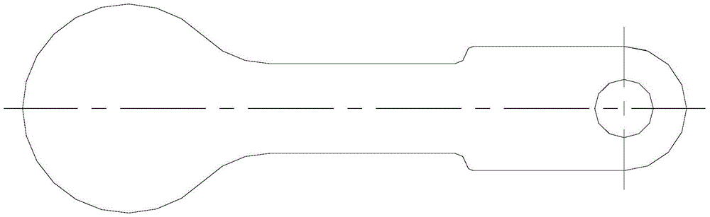
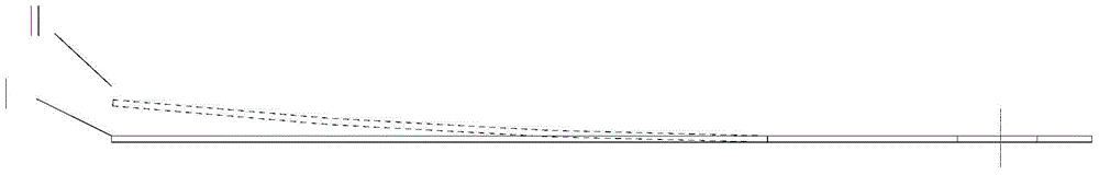
[0026] see Figure 4 , the present invention provides a compressor valve plate 100, comprising a valve plate head 110, a valve plate tail 120 and a connecting portion 130, the connecting portion 130 is connected to the valve plate head 110 and the valve plate tail 120 respectively connection, wherein, the surface of the valve head 110 in this embodiment is provided with a flexible groove 111; the flexible groove 111 divides the valve head 110 into a flexible part 112 and a rigid part 113, and the One side of the rigid part 113...


PUM


Abstract

The invention discloses a compressor valve and a compressor. The compressor valve comprises a valve head, a valve tail and a connecting part, wherein the connecting part is respectively connected with the valve head and the valve tail; a flexible slot is formed in the surface of the valve head; the valve head is divided into a flexible part and a rigid part by the flexible slot, one side of the rigid part is connected with the connecting part, and the other side of the rigid part is connected with the flexible part through the flexible slot. According to the compressor valve, the gas discharge resistance can be well remitted, and the gas in the shell cannot flow backwards into an air cylinder, thus the energy consumption of the compressor is reduced, the cooling capacity of the compressor is increased and the performance of the compressor is improved.

Description

technical field [0001] The invention relates to the field of compressors, in particular to a compressor valve plate and a compressor comprising the compressor valve plate. Background technique [0002] At present, the compressor valve plate used on the compressor is generally figure 1 The flap valve shown. Its working process is as figure 2 As shown, in one operating cycle of the compressor, when the compressor is about to complete the exhaust process and is about to close, the pressure of the shell is greater than the exhaust pressure, at this time the tongue valve cannot be effectively sealed, so the gas in the shell flows into the cylinder In the cavity, the cooling capacity of the compressor is reduced, the power consumption is increased, and the performance of the compressor is reduced. Contents of the invention [0003] In view of the above-mentioned problem of shell gas backflowing into the cylinder chamber, the object of the present invention is to provide a ne...

Claims


Application Information

Patent Timeline
Patent Type & Authority Patents(China)
IPC IPC(8): F04B39/10
Inventor 程剑国范少稳潘登崔雪梅詹大强
Owner GREE ELECTRIC APPLIANCES INC
Why Eureka
Try Eureka