Parallel flow heat exchanger

A parallel flow heat exchanger and header technology, which is applied in evaporator/condenser, lighting and heating equipment, refrigeration components, etc., can solve the problems of low heat exchange efficiency and uneven distribution of refrigerant, and achieve heat exchange The effects of improved efficiency, simple and reasonable processing technology and structure, and uniform temperature distribution

Inactive Publication Date: 2015-07-08
GD MIDEA AIR-CONDITIONING EQUIP CO LTD +1
View PDF9 Cites 7 Cited by
  • Summary
  • Abstract
  • Description
  • Claims
  • Application Information

AI Technical Summary

Problems solved by technology

[0004] The purpose of the present invention is to provide a parallel flow heat exchanger, which aims to solve the problem of low heat exchange effi

Method used


Image

  • Parallel flow heat exchanger
  • Parallel flow heat exchanger
  • Parallel flow heat exchanger

Examples


Embodiment Construction

[0027] In order to make the object, technical solution and advantages of the present invention clearer, the present invention will be further described in detail below in conjunction with the accompanying drawings and embodiments. It should be understood that the specific embodiments described here are only used to explain the present invention, not to limit the present invention.

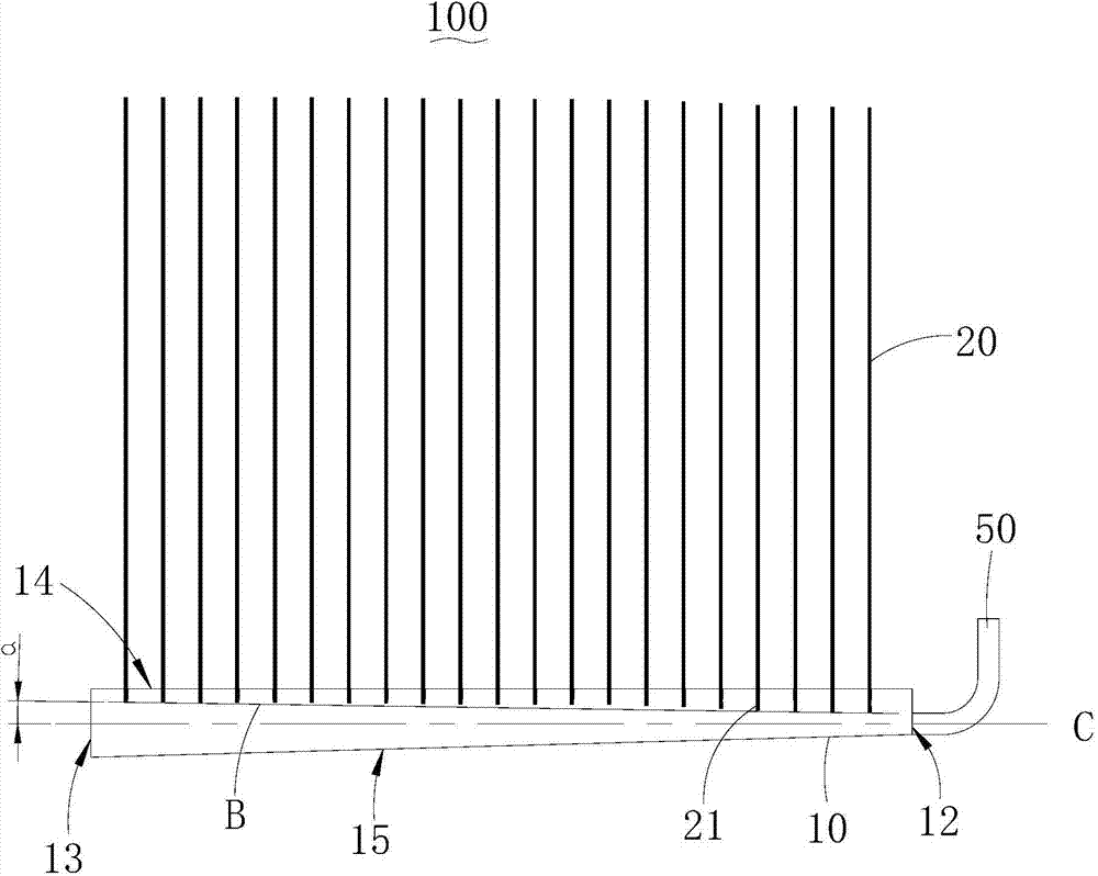
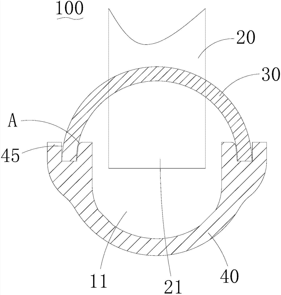
[0028] see figure 1 and figure 2 , the parallel flow heat exchanger 100 provided by the first embodiment of the present invention includes a header 10, a plurality of flat tubes 20 inserted in the header 10, and connected between adjacent flat tubes 20 fins (not shown) and the refrigerant tube 50 connected to the header 10, the header 10 has a first end surface 12 and a second end surface 13 opposite to the first end surface 12, so The header 10 has a first side 14 and a second side 15 opposite to the first side 14, the refrigerant pipe 50 communicates with the header 10 through the first end su...


PUM


Abstract

The invention discloses a parallel flow heat exchanger. The parallel flow heat exchanger comprises a flow collecting pipe, a plurality of flat pipes inserted in the flow collecting pipe, fins connected between adjacent flat pipes, and a refrigerant pipe communicated with the flow collecting pipe, the flow collecting pipe comprises a first head face and a second head face opposite to the first head face, the flow collecting pipe has a first side and a second side opposite to the first side, the refrigerant pipe is communicated with the inside of the flow collecting pipe through the first head face, each flat pipe enters the flow collecting pipe from the first side of the flow collecting pipe, and the distance between the enter end of each flat pipe and the second side of the flow collecting pipe is increased gradually in the direction from the first head face to the second head face. By means of the scheme, the flow rate of the medium in the flat pipe at the far end is roughly the same with the flow rate of the medium in the flat pipe at the near end, the medium in each flat pipe is sufficient, the temperature distribution of the parallel flow heat exchanger at different positions is uniform, and the heat exchange efficiency of the parallel flow heat exchanger device is greatly improved.

Description

technical field [0001] The invention belongs to the technical field of air-conditioning heat exchangers, in particular to a parallel flow heat exchanger. Background technique [0002] China is a country rich in aluminum resources but deficient in copper resources. The energy efficiency standards of air conditioners are increasing year by year, which will inevitably consume a large amount of copper resources, resulting in the rapid rise of copper prices and the risk of shortage of copper resources. Therefore, the technology of replacing copper with aluminum will become an inevitable trend in the development of air-conditioning heat exchangers in the future. [0003] Parallel flow heat exchanger is a kind of all-aluminum heat exchanger, which is more and more widely used as a new type of heat exchanger for air conditioners. However, when the existing parallel flow heat exchanger is used as an evaporator, since the evaporating medium is in a gas-liquid two-phase state after e...

Claims


Application Information

Patent Timeline
IPC IPC(8): F25B39/00
CPCF25B39/028
Inventor 李丰喻广南
Owner GD MIDEA AIR-CONDITIONING EQUIP CO LTD
Why Eureka
Try Eureka