Dehydrator used in cooling tower

A technology for cooling towers and water heaters, applied in water shower coolers, heat exchanger types, direct contact heat exchangers, etc. Improve water removal efficiency, improve water removal effect, and save water resources

Inactive Publication Date: 2015-07-08
汤子仁
View PDF5 Cites 6 Cited by
  • Summary
  • Abstract
  • Description
  • Claims
  • Application Information

AI Technical Summary

Problems solved by technology

[0002] There are many cooling towers used in power plants, chemical plants, etc., and the cooling water consumption is huge. The water eliminator installed in the cooling tower is used to recover the small water droplets in the hot and humid air discharged from the cooling tower, and play a role in water retention. 1. Prevent water from splashing everywhere. If there is no water eliminator, it will be like light rain next to the cooling tower. The evaporation and splashing of water are serious, which is not only a waste of water resources, but also not environmentally friendly, and affects the surrounding environment
The previous cooling tower eliminator has a simple structure, is easy to deform, has poor water removal effect, and is prone to rising water vapor, which not only causes the loss of circulating water and wastes resources, but also the rising water vapor corrodes metal parts, which seriously increases the frequency of cooling tower maintenance and causes maintenance cycles. shortened, the use cost increases; the connection is complicated, and the installation project is long and difficult
The water eliminator in the prior art is composed of a water removal sheet, and the water removal sheet includes two ends and a central wave peak. The water removal effect has been improved to a certain extent, but most of the water vapor still enters the environment

Method used


Image

  • Dehydrator used in cooling tower

Examples


Embodiment Construction

[0014] The present invention will now be further described in conjunction with specific examples, and the following examples are intended to illustrate the present invention rather than further limit the present invention.

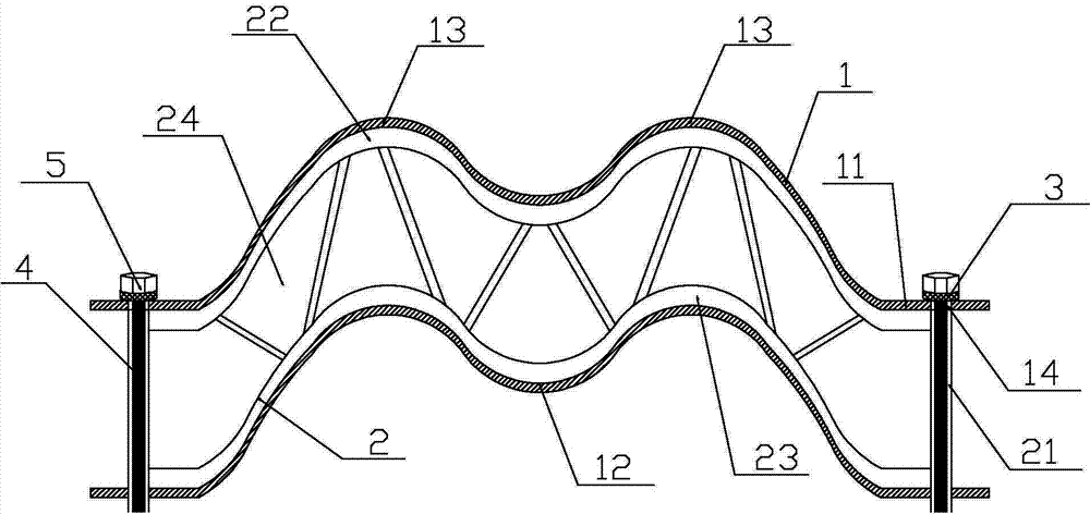
[0015] Such as figure 1 As shown, a water eliminator for a cooling tower is assembled from several water removal sheets 1, brackets 2, positioning rings 3, pull rods 4 and nuts 5. The water removal sheets 1 are corrugated, and the water removal sheets 1 include two Two ends 11, a central trough 12 and two crests 13 located on both sides of the trough 12, the bracket 2 is located between the two water removal sheets 1, the bracket 2 is composed of a column 21, an upper corrugated plate 22, a lower corrugated plate 23 and heat dissipation Holes 24, column 21 is located at both ends of the bracket 2, and the column 21 is a hollow structure, the cooling hole 24 is located between the upper corrugated plate 22 and the lower corrugated plate 23, the tie rod 4 pe...


PUM


Abstract

The invention relates to a dehydrator, in particular to a dehydrator used in a cooling tower. The dehydrator used in the cooling tower is formed by assembling a plurality of dehydrating sheets, a bracket, a positioning ring, a pull rod and a nut, wherein the dehydrating sheets are corrugated; each dehydrating sheet comprises two end parts, a middle wave trough and two wave crests at the two sides of the wave trough; the bracket is positioned between the two dehydrating sheets; the bracket comprises stand columns, an upper corrugated plate, the lower corrugated plate and radiating holes; the stand columns are positioned at the two ends of the bracket, and the stand columns are hollow structures; the radiating holes are positioned between the upper corrugated plate and the lower corrugated plate; the pull rod penetrates into the hollow structures of the stand columns, positioning rings sleeve the two ends of the pull rod, and the two ends of the pull rod are fixed by nuts. According to the dehydrator disclosed by the invention, the dehydrating efficiency and the dehydrating effects are radically improved, so that the water resources are saved, the energy is saved efficiently, and the connection is convenient and easy to dismount.

Description

technical field [0001] The invention relates to a water eliminator, in particular to a water eliminator used in a cooling tower. Background technique [0002] There are many cooling towers used in power plants, chemical plants, etc., and the cooling water consumption is huge. The water eliminator installed in the cooling tower is used to recover the small water droplets in the hot and humid air discharged from the cooling tower, and play a role in water retention. 1. Prevent water from splashing everywhere. If there is no water eliminator, it will be like light rain next to the cooling tower. The evaporation and splashing of water are serious, which is not only a waste of water resources, but also not environmentally friendly, and affects the surrounding environment. The previous cooling tower eliminator has a simple structure, is easy to deform, has poor water removal effect, and is prone to rising water vapor, which not only causes the loss of circulating water and wastes ...

Claims


Application Information

Patent Timeline
Patent Type & Authority Applications(China)
IPC IPC(8): F28F25/08
Inventor 汤子仁
Owner 汤子仁
Why Eureka
Try Eureka