Ultrasonic flowmeter

A flowmeter, ultrasonic technology, applied in the field of ultrasonic flowmeter, can solve the problems of cumbersome operation, high production cost, complex positioning structure, etc., and achieve the effect of improving precise position, convenient installation and accurate measurement

Active Publication Date: 2015-07-08
WEIHAI PLOUMETER
View PDF9 Cites 11 Cited by
  • Summary
  • Abstract
  • Description
  • Claims
  • Application Information

AI Technical Summary

Problems solved by technology

This kind of positioning structure is complicated, and it is not easy to install and clean and maintain the mirror in the later stage
[0004] In order to solve the technical problem that the reflective mirror is easy to clean, after searching, CN202501878U discloses a utility model patent for an ultrasonic heat meter flow measuring tube, CN201508256U discloses a utility model for a washable ultrasonic heat meter flow measuring tube, and CN201724699 discloses a utility model patent for a flow measuring tube of an ultrasonic heat meter. A utility model of a washable ultrasonic heat meter flow measuring tube treated with turbulence. The disadvantages of the above-mentioned patents are: complex structure, high production cost, all need to be taken out when cleaning, cumbersome operation, and because the reflective lens is glued to the reflective lens Therefore, it is impossible to thoroughly clean and maintain the reflector

Method used


Image

  • Ultrasonic flowmeter
  • Ultrasonic flowmeter
  • Ultrasonic flowmeter

Examples


Embodiment Construction

[0021] Below in conjunction with accompanying drawing, the present invention is further described:

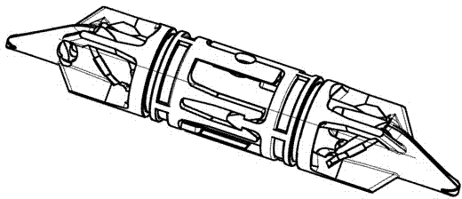
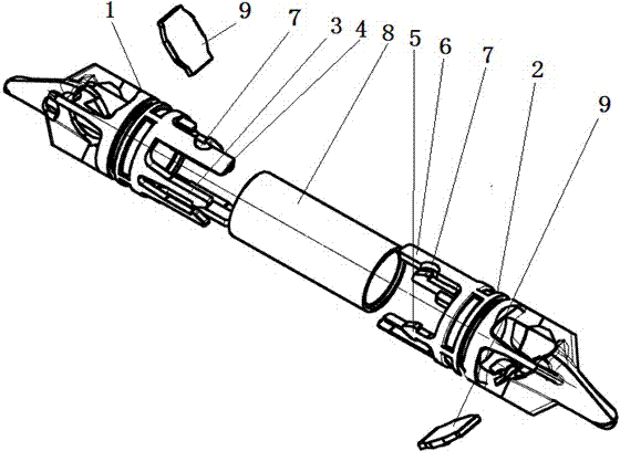
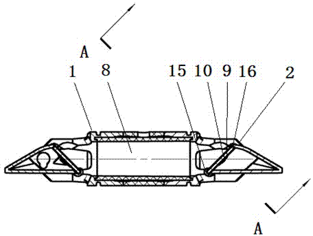
[0022] As shown in the accompanying drawings, an ultrasonic flowmeter includes a flow pipe body 19 and a set screw 20. The flow pipe body is provided with a measuring pipe section 8, a reflector mounting seat and a reflector lens 9, and the reflector lens is installed on the reflector On the mounting seat, the structure on the flow pipe body is the same as that of the prior art, so it will not be described in detail here. It is characterized in that the reflector mounting seat is composed of a left reflector mounting seat 1 and a right reflector mounting seat 2. The right end of the left reflector mounting seat 1 is provided with a right positioning surface, and the outer circumferential array of the right positioning surface has at least two female buckles 3, and the left end of the right reflector mounting seat 2 is provided with a left positioning surface, and the left positi...


PUM


Abstract

The invention discloses an ultrasonic flowmeter. The ultrasonic flowmeter comprises a flow tube and a positioning screw. A measuring tube section, a reflector installation base and a reflection lens are arranged in the flow tube. The ultrasonic flowmeter is characterized in that the reflector installation base is formed by a left reflector installation base body and a right reflector installation base body, female buckles and left positioning rib plates are arrayed at the right end of the left reflector installation base body, male buckles and right positioning rib plates are arrayed at the left end of the right reflector installation base body, the measuring tube section is arranged in the female buckles, the male buckles, the left positioning rib plates and the right positioning rib plates which are buckled together, the left end of the measuring tube section abuts against the right positioning face of the left reflector installation base body, the right end of the measuring tube section abuts against the left positioning face of the right reflector installation base body, and the positioning screw is in threaded connection with the flow tube, then penetrates through top ends of semicircular positioning grooves and abuts against the measuring tube section. The ultrasonic flowmeter has the advantages of being novel in structure, convenient to install, accurate in positioning, precise in measuring, rapid to disassemble, convenient to maintain and the like.

Description

technical field [0001] The invention relates to the technical field of flow measurement, in particular to an ultrasonic flowmeter. Background technique [0002] At present, in the measurement of ultrasonic heat meters and water flow, it is mainly realized by placing one or more pairs of ultrasonic transducers at both ends of the measured pipeline. Ultrasonic flow meters use the principle of ultrasonic waves propagating in liquids. The flow velocity of the fluid is calculated by measuring the forward and reverse propagation velocity difference of the sound wave, and then the flow rate is calculated by the integral formula integrated in the PCB board chip. As long as there are direct and reflection modes of ultrasonic propagation, the reflective mirror and measuring tube are mainly fixed inside the tube body through the reflector mount. The reflector and the measuring tube are separated from each other, and there is a disadvantage that the positioning of the reflector is not...

Claims


Application Information

Patent Timeline
Patent Type & Authority Applications(China)
IPC IPC(8): G01F1/66
Inventor 付涛邓云志杜家斌
Owner WEIHAI PLOUMETER
Why Eureka
Try Eureka